

Motor connection and connenction boxes
Connection, circuit and connection boxes
Location of the connection box
The connection box of the motor can be mounted in four different locations or positions. The position of the connection box must always be viewed from the drive end (DE). The standard position of the connection box is on top, with the exception of non-standard motors in which case the standard position of the connection box is on the right-hand side.
Connection box on right-hand side – Order codeK09
Connection box on left-hand side – Order codeK10
If rotation of the connection box is possible later for motors that are supplied as standard with cast feet, it is recommended that the version “Connection box on top, feet screwed on” is recommended.
Order codeK11
The number of winding ends depends on the winding design. Three-phase motors are connected to the three phase conductors L1, L2 and L3 of a three-phase system. The rated voltage of the motor in the running connection must match the phase conductor voltages of the network.
When the three phases are operating in a time sequence and are connected to the terminals of the motor in alphabetical order U1, V1 and W1, clockwise rotation is established as viewed from the motor shaft. The direction of rotation of the motor can be reversed if two connecting leads are interchanged.
Labeled terminals are provided to connect the protective conductor.
A protective earth terminal is provided in the connection box for earthing. An earth terminal is located on the outside of the motor housing (special version in the case of 1LA5, 1LA6, 1LA7 and 1LA9 motors. Order codeL13).
If a brake control system or thermal protection is installed, the connections will also be in the connection box.
The motors are suitable for direct connection to the line supply.
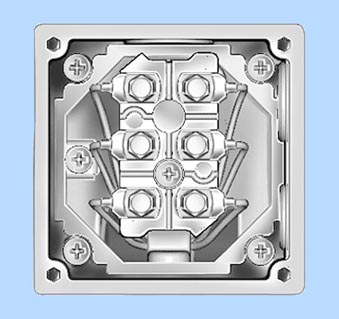
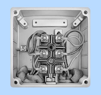
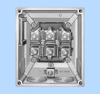
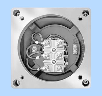
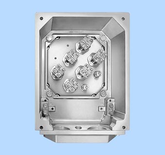
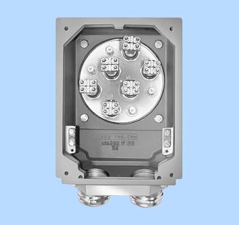
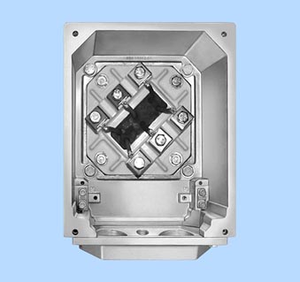
Design of the connection box
Connection boxes for motors to (E)Exn (Zone 2) type of protection and for protection against dust explosions (Zone 21) differ from the basic version. For dust explosion protection (Zone 22), the connection boxes of the basic version are used.
For 1LG4 and 1LG6 motors, frame sizes 180 to 225 and 1MA6 motors frame sizes 180 to 200, 1MJ6 frame sizes 71 to 160 M and frame sizes 180 to 200 L, a connection box is available in cast iron.
Order codeK15
For 1LA6 and 1MA6 frame size 100 – 160, 1MJ6 frame size
160 L and 1MJ7, 1MA6 frame size 225 – 315 standard version.
Not possible for 1LA7 and 1MA7.
For 1MJ motors:
The connection boxes are designed to EEx e type of protection. The ends of the windings for motors up to frame size 160 are routed through a shared explosion-proof leadthrough into the connection box; for frame size 180 and above, they are routed through single leadthroughs.
For 1MJ motors, an explosion-proof connection box with
EEx d II C type of protection is available.
Fur die 1MJ-Motoren ist ein druckfester Anschlusskasten der Zundschutzart EEx d II C entspricht erhaltlich.
Order codeK53
For motor series 1LA8, 1PQ8 and 1LL8, the ends of the windings are routed through single leadthroughs into the connection box.
The number of terminals and the size of the connection box is designed for standard requirements. For special requirements or if the customer requires a larger connection box, the connection box for the next larger frame size can be supplied.
For all motors except for non-standard motors, 1MJ6 and 1MJ7 motors: Next larger connection box
Order codeL00
For non-standard motors (motor series 1LA8, 1PQ8 and 1LL8) Next larger 1XB1 621 connection box
Order codeM58 Next larger 1XB1 631 connection box
Order codeL00
Detailed assignment of connection boxes, see page 1/42.
If the necessary installation angle of the motor would cause machine components to collide with the connection box, the connection box can be moved from the drive end (DE) to the non-drive end (NDE). Order code M64 Not possible for explosion-proof motors.
Motor connection
Line feeder cables
The line feeder cables must be dimensioned acc. to DIN VDE 0298. The number of required feeder cables, if necessary in parallel, is defined by:
- The max. cable cross-section which can be connected
- The cable type
- Routing
- Ambient temperature and the corresponding maximum current in accordance with DIN VDE 0298
Cable entry on connection box
Unless stated otherwise, the cable entry is located in the standard position as shown in the illustration below.
The connection box can also be rotated such that the cable entry is located
- Towards the drive end (DE) (rotation of connection box by 90°, entry from DE)
Order codeK83 - Towards the non-drive end (NDE) (rotation of connection box by 90°, entry from NDE)
Order codeK84
With optionsK83andK84, 1LA7 motors of frame sizes 100 to 160 require an additional connection box upper section. This measure results in increased height of the connection box. The dimension AD increases by approx. 30 mm, dimension AF changes depending on the frame size by between 45 and 47 mm. For the precise values of AD and AF, see “Dimension drawings” in the corresponding sections of the catalogue.
If the cable entry is rotated by 180°, special measures are required for 1LA7 and 1LA5 motors of frame sizes 63 to 90 as well as 180 to 225 (without a change in dimensions). (Rotation of the connection box by 180°)
Order codeK85
From frame size 100 to 160, the break-outs in the connection box can be used.
The dimensions of the connection box are listed in the relevant sections of the catalogue in accordance with the frame size and the “Dimension drawings”.
If the position of the connection box (connection box RHS, LHS or above) is changed, the position of the cable entry must be checked and, if necessary, it can be ordered with the corresponding order codes (K83;K84;K85).
Ordering example
Connection box RHS (Order codeK09):
If no other order code is specified: Cable entry from below the motor.
With additional order codeK85:
Cable entry from drive end (DE)

For cable entry to a standard connection box, acable gland can be ordered for motor connection.
Cable entry, standard configuration
Order codeK54
For cable entry to a connection box with the options of motor protection or anti-condensation heating,two cable glands will be supplied.
Cable entry, maximum configuration
Order codeK55
For non-standard motors (motor series 1LA8, 1PQ8 and 1LL8), the cable entry can be implemented in accordance with DIN 89280 for the maximum possible configuration of cable entries in the connection box.
Order codeK57
A two-part plate on the connection box can be supplied if required.
Order codeK06
For special requirements for which the standard holes for the cable entries are inadequate, too large or when the routing must be implemented differently, an undrilled entry plate can be supplied to allow holes to be drilled as required on assembly.
Order codeL01
Protruding cable ends
For confined spaces, protruding cable ends can be ordered, without a connection box with cover plate.
For protruding cable ends for smoke extraction motors, see the “Smoke extraction motors” section of the catalogue.
The following lengths of protruding cables can already be ordered using order codes on request:
- 3 cables protruding, 0.5 m long
Order codeL44 - 3 cables protruding, 1.5 m long
Order codeL45 - 6 cables protruding, 0.5 m long
Order codeL47 - 6 cables protruding, 1.5 m long
Order codeL48 - 6 cables protruding, 3.0 m long
Order codeL49
It is also possible to rotate the position of the three protruding cables:
- Cable connection on right side, as viewed from drive end (DE)
Order codeL51 - Cable connection on left side, as viewed from non-drive end (NDE)
Order codeL52
For 1LG4/1LG6/1LP4/1PP4 motors, it is also possible to order the length of protruding cable in plian text with order codesL51andL52.
In combination with winding monitoring (Order codeA11, A12, A15, A16, A23, A25 or A31) or anti-condensation heating (Order codeK45 orK46), optionL44, L45, L47, L48 orL49must be specified twice on ordering.
Position of protruding cables
Motor series 1LA7Frame sizes 56 to 160: As standard, above at drive end (DE).
Motor series 1LA6Frame sizes 100 to 160: As standard, above at drive end (DE).
Motor series 1LA5Frame sizes 180 to 225: As standard, above at drive end (DE).
Motor series 1LA9Frame sizes 56 to 90: As standard, above at drive end (DE). Frame sizes 100 to160: Viewed from drive end, as standard at drive end (DE) on right. Frame sizes 180 to 200: As standard, above at drive end (DE).
Motor series 1LG4/1LG6/1LP4/1PP4Frame sizes 180 to 315: As standard, above at drive end (DE). Optionally left or right at drive end (DE)
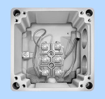
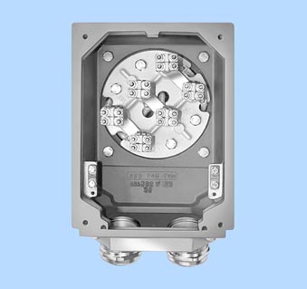
Connection, circuit and connection boxes
Type gk 030 |
Type gk 127 |
Type gk 130, gk 230, gk 330 |
|---|---|---|
|
|
|
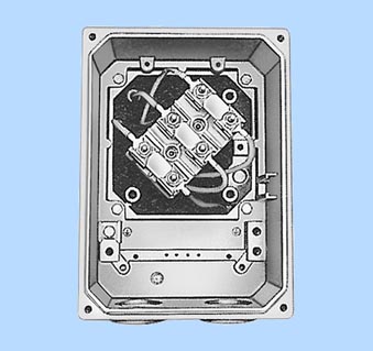
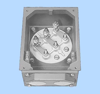
Type gk 330 (for 1LA5, 1LG4, 1LG6) |
Type gk 135, gk 235, gk 335 |
Type gk 430, gk 431 |
|
|
|
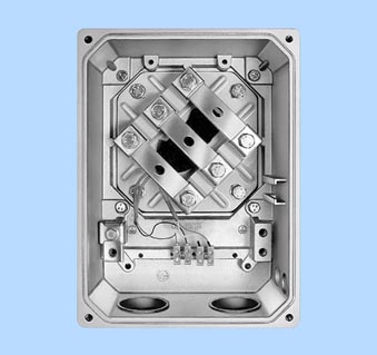
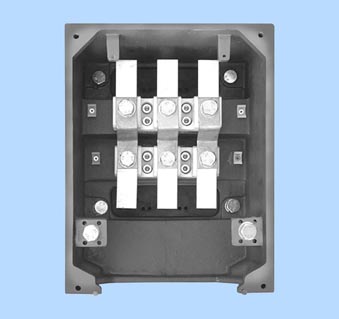
Type 1XB7 222 |
Type gt 520, gt 540, gt 620, gt 640 |
Type 1XB7 422, 1XB7 522 |
|
|
|
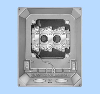
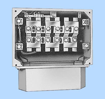
Type 1XB7 622 |
Type 1XB1 621 |
Type 1XB1 631 |
|
|
|
Type gk 465 |
Type 1XC1 270, 1XC1 380 |
Type 1XC1 480, 1XC1 580 |
|
|
|
Type 1XB7 322 |
||
|
Connection boxes for 1LA, 1LG, 1LP and 1PP motors
Motors |
Frame size |
Number of cable entries |
Connection box material |
Feeder connection |
|---|---|---|---|---|
1LA7, 1LA9 1LP7, 1PP7 |
56 ... 71 |
2 cable glands incl. |
Aluminum alloy |
Without cable lug or |
80 ... 90 |
||||
100 ... 160 |
2 holes 180° apart, |
|||
1LA5, 1LA9 1LP5, 1PP5 |
180 ... 225 |
2 holes with plugs |
||
1LA6 |
100 ... 160 |
Cast iron |
||
1LG4, 1LG6 1LP4, 1PP4, 1PP6 |
180 ... 200 |
Aluminium alloy1) |
Without cable lug | |
225 |
With cable lug | |||
250 ... 315 |
Cast iron |
|||
1LA8, 1PQ8, 1LL8 |
315 ... 355 2) 3) |
|||
400 ... 450 |
4 holes with plugs |
1) Connection box in cast-iron version K15.
2) 15° to the vertical in each case
3) Frame sizes 357-2 and 357-4 as for frame sizes 400 and 450
Possible positions of connection boxes for 1LA, 1LG, 1LP and 1PP motors
Motors |
Frame size |
Connection box position |
Rotation of connection box | ||||
|---|---|---|---|---|---|---|---|
top |
Side, right or left |
Retrofitting possible |
90°4) |
180°4) |
Retrofitting possible | ||
1LA5, 1LA7, 1LA9 1LP5, 1LP7 1PP5, 1PP7 |
56 ... 71 |
° |
– |
– |
° |
° |
Yes |
80 ... 90 |
° |
° |
– |
° |
° |
Yes | |
100 ... 160 |
° |
° |
– |
–5) |
° |
Yes | |
180 ... 225 |
° |
° |
– |
° |
° |
Yes | |
1LA6 |
100 ... 160 |
° |
° |
– |
° |
° |
Yes |
1LG4, 1LG6 1LP4, 1PP4, 1PP6 |
180 ... 315 |
° |
° |
–6) |
° |
° |
Yes |
1LA8 |
315 |
° |
° 2) |
– |
° |
° |
– |
355 |
° |
° 2) |
– |
° |
° |
– | |
400, 450 |
° |
° 2) |
– |
° |
° |
– | |
° Available version
For further details of 1LA8 motors, see “Dimensions”, “1LA8”.
Connection boxes for 1LA, 1LG, 1LL, 1LP, 1PP and 1PQ motors in standard version and for Zone 22
See the next section of the catalogue for connection boxes for 1LA8, 1PQ8 and 1LL8.
Frame size |
Connection box |
Number of terminals |
Contact screw thread |
Max. conductor size |
Sealing range |
Cable entry 1) 2) |
Two-part plate 3) Max. outer cable diameter |
|---|---|---|---|---|---|---|---|
Type |
mm2 |
mm |
Size |
mm | |||
1LA5, 1LA7, 1LA9, 1LP5, 1LP7, 1PP5 and 1PP7 | |||||||
56 |
gk030 (gk127)4) |
6 |
M4 |
1.5 (2.5 with cable lug) |
9...17 4.5...10 |
M25x1.5 M16x1.5 |
|
63 |
|||||||
71 |
|||||||
80 |
|||||||
90 |
|||||||
100 |
gk130 |
6 |
M4 |
4 |
11...21 |
M32x1.5 |
|
112 |
|||||||
132 |
gk230 |
6 |
M4 |
6 |
11...21 |
M32x1.5 |
|
160 |
gk330 |
6 |
M5 |
16 |
19...28 |
M40x1.5 |
|
180 |
|||||||
200 |
gk430 |
6 |
M6 |
25 |
27...35 |
M50x1.5 |
|
225 |
gk431 |
6 |
M8 |
35 |
27...35 |
M50x1.5 |
|
1LA6 | |||||||
100 |
gk135 |
6 |
M4 |
4 |
11...21 |
M32x1.5 |
|
112 |
|||||||
132 |
gk235 |
6 |
M4 |
6 |
11...21 |
M32x1.5 |
|
160 |
gk335 |
6 |
M5 |
16 |
19...28 |
M40x1.5 |
|
1LG4, 1LG6, 1LP4, 1PP4 and 1PP6 | |||||||
180 |
gk330 |
6 |
M5 |
16 |
19...28 |
M40x1.5 |
|
200 |
gk430 |
6 |
M6 |
25 |
27...35 |
M50x1.5 |
|
225 |
gk431 |
6 |
M8 |
35 |
27...35 |
M50x1.5 |
|
250 |
gt 520 |
6 |
M10 |
120 |
34...42 |
M63x1.5 |
|
280 |
|||||||
315 |
gt 620 |
6 |
M12 |
2405) |
38...45 |
M63x1.5 |
|
The connection box table does not apply to pole-changing motors with three speeds.
1) Designed for cable glands with O-ring.
2) For 1LA7 motors frame sizes 100 to 160, speed nuts are enclosed for the cable glands.
3) A two-part plate is available. Order code K06. Standard version for 1XB1 631 connection box. For frame size 250 M and above, with strain relief.
4) (gk 127) For frame sizes 63 to 90, with additional installation of several temperature sensors, order code A12 or a brake, a larger connection box will be necessary. The specified values do not change.
5) With cable cross-sections ?240 mm2, it is recommended that the next larger connection box is used (Order code L00). Alternatively, order a two-part plate (Order code K06).
Connection boxes for 1LA8 and 1PQ8 motors in standard version
Line-fed operation
Frame size |
Connection |
Number of terminals |
Contact screw |
Max. rec. conductor cross- section |
Outer cable diameter (sealing range) |
Cable |
Cable gland optionK57 7) |
Auxiliary lead |
Two-part plate optionK06 | |||
|---|---|---|---|---|---|---|---|---|---|---|---|---|
Outer cable diameter |
Cable entry |
Permissible outer cable diameter |
Cable |
Auxiliary lead outer cable diameter | ||||||||
Type |
mm2 |
mm |
Size |
Size |
mm |
Size |
mm |
Size |
mm | |||
1LA8... 1PQ8... | ||||||||||||
. . . . 315 |
gt 640 8) 9) 11) |
6 |
M12 |
185 |
41.0 ... 56.5 |
2 x M72x2 + |
2 x M72x2 |
7 ... 13 |
2 x M20x1.5 |
– |
– |
– |
. . . . 353 |
1XB1 621 |
6 |
M16 |
240 |
56.0 ... 68.5 |
2 x M80x2 + |
2 x M80x2 |
11.5 ... 15.5 |
2 x M25x1.5 |
40 ... 70 |
2 x D80 + |
11.5 ... 15.5 |
. . . . 357-2 |
1XB1 631 10) |
12 |
M16 |
240 |
56.0 ... 68.5 |
4 x M80x2 + |
4x M80x2 |
11.5 ... 15.5 |
2 x M25x1.5 |
40 ... 75 |
4 x D80 + |
11.5 ... 15.5 |
. . . . 357-4 |
1XB1 634 10) |
|||||||||||
1) Others available on request.
2) Shielded cable (EMC); with option K57, the cable glands can be supplied.
3) With option L00, the motor can be supplied with the 1XB1 631 connection box (recommended for cable cross-sections ?240 mm2).
4) Cable entry without removable plate, cable entry in connection box casing.
5) Cable entry with removable plate or supports.
6) With option M58, the motor can be supplied with the 1XB1 621 connection box (recommended for cable cross-sections >185 mm2).
Converter-fed operation
Frame size |
Connection box |
Number of terminals |
Contact screw thread |
Max. rec. conductor cross-section |
Outer cable diameter (sealing range) |
Cable |
Cable gland optionK57 2) |
Auxiliary lead | |
|---|---|---|---|---|---|---|---|---|---|
Outer cable diameter |
Cable gland optionK572) | ||||||||
Type |
mm2 |
mm |
Size |
Size |
mm |
Size | |||
1LA8... 1PQ8... | |||||||||
. . . . 315 |
gt 640 3) 4) 6) |
6 |
M12 |
185 |
41.0 ... 56.5 |
2 x M72x2 + |
2 x M72x2 |
9 ... 13 |
2 x M20x1.5 |
. . . . 353 |
1XB1 621 3) 5) |
6 |
M16 |
240 |
56.0 ... 68.5 |
2 x M80x2 + |
2 x M80x2 |
11 ... 16 |
2 x M25x1.5 |
. . . . 357-6 |
1XB1 634 3) 5) |
||||||||
....357-2 |
1XB16315) |
12 |
M16 |
240 |
56.0...68.5 |
4xM80x2+ 2xM25x1.5 |
4xM80x2 |
11...16 |
2xM25x1.5 |
....357-4 ....40. ....45. |
1XB16345) |
||||||||
1) Others available on request.
2) Shielded cable (EMC); with option K57, the cable glands can be supplied.
3) With option L00, the motor can be supplied with the 1XB1 631 connection box (recommended for cable cross-sections ?240 mm2).
4) Cable entry without removable plate, cable entry in connection box casing.
5) Cable entry with removable plate or supports.
6) With option M58, the motor can be supplied with the 1XB1 621 connection box (recommended for cable cross-sections >185 mm2).
Connection boxes for 1LL8 motors in standard version
Line-fed operation
Frame size |
Connection box |
Number of terminals |
Contact screw thread |
Max. rec. conductor cross- section |
Outer cable diameter (sealing range) |
Cable |
Cable gland optionK57 7) |
Auxiliary lead |
Two-part plate optionK06 | |||
|---|---|---|---|---|---|---|---|---|---|---|---|---|
Outer cable diameter |
Cable gland |
Permissible outer cable diameter |
Cable entry |
Auxiliary lead | ||||||||
Type |
mm2 |
mm |
Size |
Size |
mm |
Size |
mm |
Size |
mm | |||
1LL8... | ||||||||||||
. . . . 31 . |
1XB1 621 |
6 |
M16 |
240 |
56.0 ... 68.5 |
2 x M80x2 + |
2 x M80x2 |
11.5 ... 15.5 |
2 x M25x1.5 |
40 ... 70 |
2 x D80 + |
11.5 ... 15.5 |
. . . . 35 . |
1XB1 631 5) |
12 |
M16 |
240 |
56.0 ... 68.5 |
4 x M80x2 + |
4 x M80x2 |
11.5 ... 15.5 |
2 x M25x1.5 |
40 ... 75 |
4 x D80 + |
11.5 ... 15.5 |
. . . . 40 . |
1XB1 634 5) |
|||||||||||
1) Others available on request.
2) Shielded cable (EMC); with option K57, the cable glands can be supplied.
3) With option L00, the motor can be supplied with the 1XB1 631 connection box (recommended for cable cross-sections ?240 mm2).
4) Cable entry without removable plate, cable entry in connection box casing.
Converter-fed operation
Frame size |
Connection box |
Number |
Contact |
Max. rec. conductor |
Outer cable diameter |
Cable |
Cable gland |
Auxiliary lead | |
|---|---|---|---|---|---|---|---|---|---|
Outer cable diameter |
Cable gland | ||||||||
Type |
mm2 |
mm |
Size |
Size |
mm |
Size | |||
1LL8 ... | |||||||||
. . . . 31. |
1XB1 621 8) 5) |
6 |
M16 |
240 |
56.0 ... 68.5 |
2 x M80x2 + |
2 x M80x2 |
11 ... 16 |
2 x M25x1.5 |
. . . . 35 . |
1XB1 631 5) |
12 |
M16 |
240 |
56.0 ... 68.5 |
4 x M80x2 + |
4 x M80x2 |
11 ... 16 |
2 x M25x1.5 |
. . . . 40 . |
1XB1 634 5) |
||||||||
1) Others available on request.
2) Shielded cable (EMC); with option K57, the cable glands can be supplied.
3) With option L00, the motor can be supplied with the 1XB1 631 connection box (recommended for cable cross-sections ?240 mm2).
4) Cable entry without removable plate, cable entry in connection box casing.
Connection boxes for 1MA6 and 1MA7 explosion-proof motors and for 1LA6/7/9 and 1LG4/6 motors in (E) Ex n version or for Zone 2 and Zone 21
Motors |
Frame size |
Number of cable entries |
Connection box material |
Feeder connection |
|---|---|---|---|---|
1MA7, 1LA7, 1LA9 |
561) ... 90 |
2 holes incl. 1 certified cable gland |
Aluminum alloy |
Without cable lug 2) or |
100 ... 160 |
4 holes incl. 1 certified cable gland |
|||
1MA6, 1LA6 |
100 ... 160 |
2 holes incl. 1 certified cable gland |
Cast iron |
|
1MA6, 1LA9 |
180 ... 200 |
2 holes incl. 1 certified cable gland |
Aluminum alloy |
|
225 |
2 holes with 2 certified cable glands |
Cast iron |
||
250 ... 315 |
||||
1LG4,1LG6 |
180...225 |
2 holes incl. 1 certified cable gland with sealing washer and 1 certified plug |
Aluminum alloy |
|
250...315 |
2 holes with 2 certified cable glands with sealing washer |
Cast iron |
1) 1MA7 motor series as well as 1LA7/1LA9 motor series in Zone 2, only frame size 63 and above.
2) The components required for connection without cable lugs are supplied with motors of frame size 225 and above as an accessory pack in the connection box.
Connection boxes for 1LA8 and 1PQ8 explosion-proof motors in (E) Ex version or for Zone 2 and Zone 22
Motors |
Frame size |
Number of cable entries |
Connection box material |
Feeder connection |
|---|---|---|---|---|
1LA8, 1PQ8 |
315, 355 3) 4) |
Undrilled cable entry |
Cast iron |
With cable lug |
400, 450 |
1) 15° to the vertical in each case.
2) Frame sizes 357-2 and 357-4 as for frame sizes 400 and 450.
Connection boxes for 1LA8 and 1PQ8 explosion-proof motors in (E) Ex version or for Zone 2 and Zone 22
Frame size |
Connection box |
Number of terminals |
Contact screw thread |
Recommended max. conductor cross-section |
Cable entry5) |
Two-part plate optionK06 | ||
|---|---|---|---|---|---|---|---|---|
Max. outer cable diameter |
Cable entry |
Auxiliary lead outer cable diameter | ||||||
Type |
mm2 |
Size |
mm |
Size |
mm | |||
1LA8 ... 1PQ8 ... | ||||||||
.... 315 .... 317 |
1XB1 621 6) 7) |
6 |
M16 |
240 |
Undrilled cable entry |
40 … 70 |
2 x D80 + 2 x M25x1.5 |
11.5 … 15.5 |
.... 353 .... 355 .... 357-6 .... 357-8 |
1XB1 6216)8) |
6 |
M16 |
240 |
Undrilled cable entry |
40 … 70 |
2 x D80 + 2 x M25x1.5 |
11.5 … 15.5 |
.... 357-2 .... 357-4 .... 40. .... 45. |
1XB1 6318) |
12 |
M16 |
240 |
Undrilled cable entry |
40 … 75 |
4 x D80 + 2 x M25x1.5 |
11.5 … 15.5 |
1) Others available on request.
2) Shielded cable (EMC); with option K57, the cable glands can be supplied.
3) With option L00, the motor can be supplied with the 1XB1 631 connection box (recommended for cable cross-sections ?240 mm2).
4) Cable entry without removable plate, cable entry in connection box casing.
Possible positions of connection boxes for 1MA6 and 1MA7 explosion-proof motors and for 1LA6 and 1LA7 motors in (E) Ex n version or for Zone 2 and Zone 21
Motors |
Frame size |
Connection box position |
Rotation of connection box | ||||
|---|---|---|---|---|---|---|---|
Above |
Side, right or left |
Retrofitting possible |
90° 9) |
180° 9) |
Retrofitting possible | ||
1MA7 and 1LA7 in Zone 2, 21 |
56 10) ... 71 |
° |
– |
– |
° |
° |
Yes |
80 ... 90 |
° |
° |
– |
° |
° |
Yes | |
100 ... 160 |
° |
° |
° |
– |
° 11) |
Yes | |
1MA6 and 1LA6 in Zone 2, 21 |
100 ... 160 |
° |
° |
° |
° |
° |
Yes |
180 ... 225 |
° |
° |
– |
° |
° |
Yes | |
250 ... 315 |
° |
° |
– |
° |
° |
Yes | |
° Available version
1) Designed for cable glands with O-ring.
2) 1MA7 motor series as well as 1LA7/1LA9 motor series in Zone 2, only frame size 63 and above.
3)From frame size 100.
Standard connection boxes for 1MA6, 1MA7 explosion-proof motors and for 1LA6, 1LA7, 1LA9, 1LG4 and 1LG6 motors in (E) Ex n, VIK version, Zone 2 and Zone 21
Frame size |
Connection box |
Number of terminals |
Contact screw thread |
Max. connectable |
Sealing range |
Cable entry1) |
Two-part plate Max. outer cable diameter |
|---|---|---|---|---|---|---|---|
Type |
mm2 |
mm |
Size |
mm | |||
1MA7, LA7, 1LA9 | |||||||
562) |
gk130 |
6 |
M4 |
4 |
9...17 4.5...10 |
M25x1.5 M16x1.5 |
|
63 |
|||||||
71 |
|||||||
80 |
|||||||
90 |
|||||||
100 |
14...21 |
M32x1.5 |
|||||
112 |
|||||||
132 |
gk230 |
6 |
M4 |
6 |
14...21 |
M32x1.5 |
|
160 |
gk330 |
6 |
M5 |
16 |
19...28 |
M40x1.5 |
|
180 |
1XB7222 |
6 |
M6 |
10 |
19...28 |
M40x1.5 |
|
200 |
1XB7322 |
6 |
M8 |
50 |
26...35 |
M50x1.5 |
|
1MA6, 1LA6 | |||||||
100 |
gk135 |
6 |
M4 |
4 |
14...21 |
M32x1.5 |
|
112 |
|||||||
132 |
gk235 |
6 |
M4 |
6 |
|||
160 |
gk335 |
6 |
M5 |
16 |
19...28 |
M40x1.5 |
|
180 |
1XB7222 |
6 |
M6 |
10 |
19...28 |
M40x1.5 |
|
200 |
1XB7322 |
6 |
M8 |
50 |
26...35 |
M50x1.5 |
|
225 |
|||||||
250 |
1XB7422 |
6 |
M10 |
120 |
34...42 |
M63x1.5 |
|
280 |
|||||||
315 |
1XB7522 |
6 |
M12 |
240 |
38...45 |
M63x1.5 |
|
1LG4, 1LG6 | |||||||
180 |
gt351 |
6 |
M6 |
16 |
19...27 |
M40x1.5 |
|
200 |
gt451 |
6 |
M8 |
50 |
24...35 |
M50x1.5 |
|
225 |
|||||||
250 |
gt540 |
6 |
M10 |
120 |
34...42 |
M63x1.5 |
|
280 |
|||||||
315 |
gt640 |
6 |
M12 |
240 |
38...45 |
M63x1.5 |
|
With 1MA motors, unused drilled holes must be sealed in accordance with
EN 50014.
1) Designed for cable glands with O-ring.
2) 1MA7 motor series as well as 1LA7/1LA9 motor series in Zone 2, only frame size 63 and above.
Connection boxes in EEx de IIC type of protection for explosion-proof motors 1MJ6, 1MJ7, 1MJ8 and 1MJ1
Motors |
Frame size |
Number of cable entries |
Connection box material |
Feeder connection |
|---|---|---|---|---|
1MJ6 |
71 ... 160 M |
2 holes incl. 1 certified cable gland |
Aluminum alloy |
Without cable lug 3) or |
160 L |
Cast iron |
|||
180 ... 200 |
Aluminum alloy |
|||
1MJ7 |
225 |
2 holes with 2 certified cable glands |
Cast iron |
|
250 ... 315 |
||||
1MJ8 |
355 |
2 entry threads without cable glands |
Cast iron |
|
1MJ1 |
315 ... 450 |
Welded steel |
1) The components required for connection without cable lugs are supplied with 1MJ7 motors of frame size 225 M and above as an accessory pack in the connection box.
Possible positions of the connection boxes in EEx de type of protection for explosion-proof motors 1MJ6, 1MJ7, 1MJ8 and 1MJ1
Motors |
Frame size |
Connection box position |
Rotation of connection box | ||||
|---|---|---|---|---|---|---|---|
Above |
Side, right or left |
Retrofitting possible |
90°4) |
180°4) |
Retrofitting possible | ||
1MJ6 |
71 ... 200 |
° |
° |
– |
° |
° |
Yes |
1MJ7 |
225 ... 315 |
° |
° |
– |
° |
° |
Yes |
1MJ8 |
355 |
° |
° |
– |
° |
° |
Yes |
1MJ1 |
315 ... 450 |
° |
° |
– |
° |
° |
Yes |
° Available version
1) The position of the cable entry must be specified when ordering.
Standard connection boxes in EEx de type of protection for explosion-proof motors 1MJ6, 1MJ7, 1MJ8 and 1MJ1
Frame size |
Connection box |
Number of terminals |
Contact screw thread |
Max. connectable cross-section |
Sealing range |
Cable entry 1) |
|---|---|---|---|---|---|---|
Type |
mm2 |
mm |
Size | |||
1MJ6, 1MJ7 | ||||||
71 |
gk330 |
6 |
M4 |
4 |
9...17 |
Standard: 1xM25x1.5 Version with PTC ther mistor: 1xM25x1.5 1xM16x1.5 |
80 |
||||||
90 |
gk420 |
6 |
M4 |
6 |
9...17 |
|
100 |
11...21 |
Standard: 1xM32x1.5 Version with PTC ther mistor: 1xM32x1.5 1xM16x1.5 | ||||
112 |
gk420 |
6 |
M4 |
6 |
11...21 |
|
132 |
||||||
160M |
gk420 |
6 |
M4 |
6 |
19...28 |
Standard: M40 x 1.5 Version with PTC ther mistor: 1xM40x1.5 1xM16x1.5 |
160L |
gk465 |
6 |
M5 |
16 |
||
180 |
1XC1270 |
6 |
M6 |
25 |
19...28 |
M40x1.5 |
200 |
1XC1380 |
6 |
M8 |
50 |
26...35 |
M50x1.5 |
225 |
||||||
250 |
1XC1480 |
6 |
M10 |
120 |
34...42 |
M63x1.5 |
280 |
||||||
315 |
1XC1580 |
6 |
M12 |
240 |
38...45 |
M63x1.5 |
1MJ8 | ||||||
355 |
No designation |
6 |
M16 |
120...300 |
35...753) |
M63x1.52) |
1MJ1 | ||||||
315 |
No designation |
6 |
M16 |
95...300 |
35...75 |
M63x1.5 |
355 |
No designation |
6 |
M16 |
35...300 |
35...75 |
M63x1.5 |
400 |
No designation |
6 |
M16 |
35...300 |
35...75 |
M63x1.5 |
450 |
No designation |
6 |
M20 |
70...300 |
35...75 |
M75x1.5 |
With 1MJ motors, unused drilled holes must be sealed in accordance with EN 50014.
Version with explosion-proof connection box is available, with the exception of frame sizes 180 and 200.
1) Designed for cable glands with O-ring.
2) Standard version with cable entry glands split lengthwise for 35 to 75 mm and strain relief.
Connection boxes in cast iron version (Order code K15) for motors 1LG4, 1LG6 and 1MA6, 1MJ6, 1MJ7 explosion-proof motors
Motors |
Frame size |
Number of cable entries |
Connection box material |
Feeder connection |
|---|---|---|---|---|
1MJ6 |
71 ... 160 M |
2 holes incl. 1 certified cable gland |
Cast iron |
Without cable lug 3) or with cable lug |
180 ... 200 |
||||
1LG4, |
180 ... 225 |
2 holes incl. 2 certified cable glands |
Cast iron |
Possible positions of the connection boxes in cast iron version (Order code K15) for 1LG4, 1LG6 motors and
1MA6, 1MJ6, 1MJ7 explosion-proof motors
Motors |
Frame size |
Connection box position |
Rotation of connection box | ||||
|---|---|---|---|---|---|---|---|
Above |
Side, right or left |
Retrofitting possible |
90° 4) |
180° 4) |
Retrofitting possible | ||
1MJ6 |
71 ... 80 |
° |
– |
– |
° |
° |
Yes |
90 ... 160 M |
° |
° |
– |
° |
° |
Yes | |
180 ... 200 |
° |
° |
– |
° |
° |
Yes | |
1LG4, |
180 ... 225 |
° |
° |
– |
° |
° |
Yes |
° Available version
Connection boxes in cast iron version (Order code K15) for motors 1LG4, 1LG6 and 1MA6, 1MJ6, 1MJ7 explosion-proof motors
Frame size |
Connection box |
Number of terminals |
Contact screw thread |
Max. connectable cross-section |
Sealing range |
Cable entry 1) |
|---|---|---|---|---|---|---|
Type |
mm2 |
mm |
Size | |||
1MJ6 | ||||||
71 |
gk065 |
6 |
M4 |
4 |
9...17 |
M25x1.5 |
80 |
||||||
90 |
6 |
|||||
100 |
gk065 |
6 |
M4 |
6 |
11...21 |
M32x1.5 |
112 |
gk265 |
6 |
M4 |
6 |
11...21 |
M32x1.5 |
112 |
gk465 |
6 |
M4 |
6 |
11...21 |
M32x1.5 |
132 |
||||||
160 M |
gk465 |
6 |
M4 |
6 |
19...28 |
M40x1.5 |
160L2) |
gk465 |
6 |
M5 |
16 |
19...28 |
M40x1.5 |
180 |
1XC1290 |
6 |
M6 |
25 |
24...35 |
M50x1.5 |
200 |
1XC1390 |
6 |
M8 |
50 |
24...35 |
M50x1.5 |
1LG4, 1LG6 | ||||||
180 |
gt320 |
6 |
M5 |
16 |
19...28 |
M40x1.5 |
200 |
gt420 |
6 |
M6 |
25 |
24...35 |
M50x1.5 |
225 |
gt421 |
6 |
M8 |
25 |
24...35 |
M50x1.5 |
1MA6 | ||||||
180 |
1XB7323 |
6 |
M8 |
50 |
24...35 |
M50x1.5 |
200 |
1XB7323 |
6 |
M8 |
50 |
24...35 |
M50x1.5 |
With 1MJ motors, unused drilled holes must be sealed in accordance with EN 50014.
Explosion-proof connection boxes in EEx d IIC type of protection (Order code K53) for explosion-proof motors 1MJ6, 1MJ7, 1MJ8 and 1MJ1
Motors |
Frame size |
Number of cable entries |
Connection box material |
Feeder connection3) |
|---|---|---|---|---|
1MJ6 |
71 ... 160 |
In standard version: In versions with PTC thermistors: |
Cast iron |
Without cable lug 4) or |
1MJ7 |
225 |
2 certified plugs |
Welded steel |
|
250 ... 315 |
||||
1MJ8 |
355 |
2 entry threads without cable glands |
Cast iron |
|
1MJ1 |
315 ... 450 |
Welded steel |
Possible positions of the explosion-proof connection boxes in EEx d IIC type of protection (Order code K53) for explosion- proof motors 1MJ6, 1MJ7, 1MJ8 and 1MJ1
Motors |
Frame size |
Connection box position |
Rotation of connection box | ||||
|---|---|---|---|---|---|---|---|
Above |
Side, right or left |
Retrofitting possible |
90° 5) |
180° 5) |
Retrofitting possible | ||
1MJ6 |
71 ... 80 |
° |
– |
– |
° |
° |
Yes |
90 ... 160 |
° |
° |
– |
° |
° |
Yes | |
1MJ7 |
225 ... 315 |
° |
° |
– |
° |
° |
Yes |
1MJ8 |
355 |
° |
° |
– |
° |
° |
Yes |
1MJ1 |
315 ... 450 |
° |
° |
– |
° |
° |
Yes |
° Available version

Explosion-proof connection boxes in EEx d IIC type of protection (Order code K53) for explosion-proof motors 1MJ6, 1MJ7, 1MJ8 and 1MJ1
Frame size |
Connection box |
Number of |
Contact screw thread |
Max. connectable cross-section |
Sealing range |
Cable entry |
|---|---|---|---|---|---|---|
Type |
mm2 |
mm |
Size | |||
1MJ6, 1MJ7 | ||||||
71 |
gk065d |
6 |
M4 |
4 |
Standard: 1xM25x1.5 1)Version with PTC thermistor: 1xM25x1.5 1xM20x1.5 | |
80 |
||||||
90 |
6 |
|||||
100 |
gk065d |
6 |
M4 |
6 |
Standard: 1xM32x1.5 1)Version with PTC thermistor: 1xM32x1.5 1xM20x1.5 | |
112 |
gk265d |
6 |
M4 |
6 |
||
132 |
gk465d |
6 |
M4 |
6 |
||
160M |
gk465d |
6 |
M4 |
6 |
Standard: 1xM40x1.5 1)Version with PTC thermistor: 1xM40x1.5 1xM20x1.5 | |
160L |
gk465d |
6 |
M5 |
16 |
||
225 |
1XC332. |
6 |
M8 |
50 |
2xM55x1.5 or 1xM55x1.5+1xM20x1.52) | |
250 |
1XC342. |
6 |
M10 |
120 |
2xM63x1.5or 1xM63x1.5+1x M20x1.52) | |
280 |
||||||
315 |
1XC352. |
6 |
M12 |
240 |
2xM80x2or 1xM80x2+1xM20x1.52) | |
1MJ8 | ||||||
355 |
No designation |
6 |
M16 |
16...300 |
40...57 |
2xM63x1.51) |
1MJ1 | ||||||
315 |
No designation |
6 |
M16 |
120...300 |
40...57 |
2xM63x1.51) |
355 |
No designation |
6 |
M16 |
16...300 |
40...57 |
2xM63x1.51) |
400 |
No designation |
6 |
M16 |
16...300 |
40...57 |
2xM63x1.51) |
450 |
No designation |
6 |
M20 |
16...300 |
56...68 |
2xM75x1.51) |
With 1MJ motors, unused drilled holes must be sealed in accordance with
EN 50014.
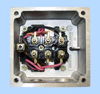
Terminal connection
The terminal board accomodates the terminals that are connected to the leads to the motor windings. The terminals are designed so that up to frame size 225, the external (line) connections can be made without the need for cable lugs. With frame size 250 and above, standard connection is with cable lugs.
For the 1LG4/1LG6/1LP4/1PP4 motor series, for frame sizes 250 to 315, stud terminals are available for connection using cable lugs (accessory pack, 3 items). Order codeM46
With frame size 250 and above, if connection without cable lugs is required, the appropriate saddle terminals for connection without cable lugs (accessory pack, 6 items) must be ordered. Order codeM47
For EExe and EExde motors, connection is generally without cable lugs.
The terminal board is permanently mounted on the housing for all motors so that if the connection box is rotated, rotation of the connections for the motor windings is prevented.
Exception:With connection boxes 1XB1 621 and 1XB1 631, the terminal support is mounted on the lower section of the connection box.
For motor series 1LA7/1LP7/1PP7 frame sizes 63 to 90, a terminal strip can be supplied for the main and auxiliary terminals.Order codeM69
Number of auxiliary terminals for 1LA, 1LG, 1LL, 1LP, 1PP and 1PQ motors – Standard version
Motor series 1LA5, 1LA6, 1LA7, 1LP5, 1LP7, 1PP5, 1PP7 have no auxiliary terminals in the standard version.
The maximum number of auxiliary terminals in the main connection box of the motor is specified. An auxiliary connection box is required when the total number of auxiliary terminals exceeds the specified values. The connections can be routed through a separate auxiliary connection box.
For motor series
- 1LA8, 1PQ8 and 1LL8 frame sizes 315 to 450
- 1MA6 frame sizes 225 to 315
- 1MJ7 frame sizes 225 to 315
the 1XB3 020 connection box is available.
Order codeL97
For non-standard motors (1LA8, 1PQ8 and 1LL8 motor series), the following can be supplied:
1XB9 016 auxiliary connection box – Order codeM50
1XB9 014 auxiliary connection box (aluminium) – Order codeM88
Type series |
Frame size |
Main connection box |
Maximum No. of auxiliary terminals |
|---|---|---|---|
1LG4, |
180 |
gk 330 |
4 |
200 |
gk 430 |
10 | |
225 |
gk 431 |
10 | |
250 |
gt 520 |
12 | |
280 |
|||
315 |
gt 620 |
16 | |
1MA6 |
225 |
1XB7 322 |
8 |
250 |
1XB7 422 |
12 | |
280 |
|||
315 |
1XB7 522 |
12 | |
1MJ7 |
225 |
1XC1 380 |
4 |
250 |
1XC1 480 |
||
280 |
|||
315 |
1XC1 580 |
6 | |
1LA8, |
315 |
gt 640 |
6 |
355 |
1XB1 621 |
12 | |
400 |
1XB1 631 |
24 | |
450 |
System ECOFAST
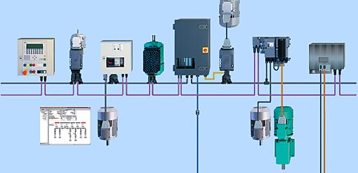
ECOFAST is a system which permits extensive decentralization and a modular structure for installation elements on the component level.
The following motor connectors are available for the separate MICROMASTER 411 frequency converter:
- ECOFAST motor connector Han Drive 10e for 230 VD/400 VY
Order code G55 - ECOFAST motor connector EMC Han Drive 10e for 230 VD/400 VY
Order code G56
In the basic version, cable entry for the ECOFAST connector
is towards the non-drive end (NDE). The dimensions of the ECOFAST motor connector depend on the motor frame size and can be read from the dimension drawing generator for motors in the “SD configurator for low-voltage motors” tool. It is particularly important to check the dimensions when a brake with a manual release lever is used towards the non-drive end (NDE) due to possible collision of the motor connector and manual release lever as well as in the direction of the drive end (DE) due to possible collision with drive units such as coupling or gear wheels.
Advantages:
The main advantages of the ECOFAST motor connector over a terminal strip are as follows:
- Fast assembly of I/O devices (e.g. motor starters) from the ECOFAST system.
- Reduction of assembly and repair times at the end user
- No wiring errors due to connector technology
- Replacement of motor without intervention in the electronics
Main features of the ECOFAST motor connector (with separate MICROMASTER 411 frequency converter):
The motor connector is mounted at the factory and replaces the connection box with terminal board. The connector is mounted towards the non-drive end (NDE). It comprises an angled motor connection casing that can be rotated by 4 x 90°. A 10-pole
(+ earth) male insert is used in the housing. In the plug-in connector, the winding connections are connected and optionally the power supply for the brake and the signal leads for the temperature sensors. The ECOFAST motor connector is compatible with the products of the ECOFAST field device system. Further information can be found in Catalog IK PI.
The mounting dimensions of this casing match those of standard industrial connectors, so it is possible to use a complete series of different standard inserts (such as Han E, ES, ESS from Harting). The motor circuit (star or delta connection) is selected in the mating connector for motor connection. The relevant jumpers are inserted by the customer in the mating connector. As a casing for the mating connector, all standard sleeve casings with lengthwise locking, frame size 10B (e.g. from Harting) can be used.
Note:
Only one sensor (temperature sensor or PTC thermistor) can be connected. The maximum permissible line voltage at the motor connector is ?500 V
Availability of the ECOFAST motor connector
The ECOFAST motor connector can be supplied for the following motor versions with the exception of the explosion-proof motors:
- Frame sizes 56 M to 132 M
- Output range 0.06 to 5.5 kW (7.5 kW on request)
- Direct on-line starting: Voltage code 1 for 230 VD/400 VY, 50 Hz
- Star-delta starting: Voltage code 9 with order code L1U 400 VD, 50 Hz
Further details:
Further information can be found in Catalogue IK PI and in Catalogue DA 51.3 “Distributed Drive Solutions MICROMASTER 411 COMBIMASTER 411” as well as on the Internet at:
http://www.siemens.com/ecofast
 Приводная техника