
Modular Technology
Basic versions
The range of potential applications for the 1LA and 1LG motors can be broadened considerably by mounting the following modules (e.g. the motors can be used as brake motors).
- 1XP8 001 rotary pulse encoder, frame sizes 71 M to 315 L
- Separately driven fan, frame sizes 100 L to 315 L
- Brake, frame sizes 63 to 315 L
The brake must always be mounted in the factory for safety reasons. The rotary pulse encoder and/or the separately driven fan can also be retrofitted.
The degree of protection of the motors with modular technology is IP55. Higher degrees of protection on request.
When a rotary pulse encoder, brake or separately driven fan is mounted, the length of the motor increases by D I. For an explanation of the additional dimensions and weights, see “Modular technology”, “Dimensions and weights”.
1XP8 001 rotary pulse encoder
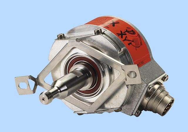
1XP8 001 rotary pulse encoder
The rotary pulse encoder can be supplied already mounted in an HTL version as1XP8 001-1 with order codeH57 or in a TTL version as1XP8 001-2 with order codeH58. The rotary pulse encoder can only be mounted on a standard non-drive end (NDE), i.e. a second shaft extension or protective cover cannot be supplied.
It can also be ordered separately and retrofitted (please enquire beforehand), Order No.1XP8 001-1 or1XP8 001-2 (see the section “Standard motors”, “Accessories and spare parts”).
The 1XP8 001 rotary pulse encoder is suitable for standard applications. For further encoders, see “Special technology” from Page /.
All 1LA5, 1LA6 and 1LA7 motors with frame sizes 100 L to 225 M that are listed in the catalogue are prepared for fitting a rotary encoder on the non-drive end (NDE) with an M8 centre hole, form DR.
All 1LG4 and 1LG6 motors that are listed in the catalogue have an M16 centre hole, form DS on the non-drive end (NDE). When a rotary pulse encoder is mounted, the length of the motor increases by D I. For an explanation of the additional dimensions and weights, see “Modular technology”, “Dimensions and weights”.
The rotary pulse encoders of “Modular technology” and “Special technology” are fitted as standard with a protective cover made of plastic. A protective cover made of non-corrosive sheet steel is available for 1LA5, 1LA6 and 1LA7 motors, see “Mechanical protection for encoders”, order codeM68, under “Special technology”.

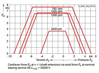
Mounting dimensions of 1XP8 001 rotary pulse encoder
Technical data of rotary pulse encoders | ||
|---|---|---|
Supply voltageUB |
1XP8 001-1 (HTL version) |
1XP8 001-2 (TTL version) |
Current input without load |
200 mA |
150 mA |
Maximum load current per output |
max. 100 mA |
max. 20 mA |
Pulses per revolution |
1024 |
1024 |
Outputs |
2 square-wave pulses A, B – 2 inverted square-wave pulses A, B | |
Pulse offset between the two outputs |
90° ±20 % |
90° ±20 % |
Output amplitude |
U
High >UB –3,5 V |
U
High >2,5 V |
Minimum edge interval |
0,8 ?s at 160 kHz |
0,45 ?s at 300 kHz |
Edge steepness |
t +,t– 200 ns |
t +,t– 100 ns |
Maximum frequency |
160 kHz |
300 kHz |
Maximum speed |
9000 rpm |
12000 rpm |
Temperature range |
–20 to +80 °C |
–20 to +100 °C |
Degree of protection |
IP66 |
IP66 |
Maximum radial cantilever force |
60 N |
60 N |
Maximum axial force |
40 N |
40 N |
Termination system |
12-pin connector (mating connector is supplied) | |
Certification |
CSA, UL |
CSA, UL |
Weight |
0,3 kg |
0,3 kg |
Seprately driven fan
The use of a separately driven fan is recommended to increase motor utilisation at low speeds and to limit noise generation at speeds significantly higher than the synchronous speed. Both of these results can only be achieved with converter-fed operation. Please enquire about traction and vibratory operation.
The separately driven fan can be supplied already fitted, order codeG17.
It can also be ordered separately and retrofitted. For selection information and order numbers, see the section “Standard motors”, “Accessories and spare parts”). A rating plate listing all the important data is fitted to the separately driven fan. The supply voltage of the 1PP9 motors with mounted separately driven fan is adapted to the voltage of the 1LG motor for voltages outside the rated voltage range. Please note the direction of rotation of the separately driven fan (axial-flow fan) when connecting it. Ambient temperature ATmax. 50 °C, please enquire for higher ambient temperatures.
When a separately driven fan is mounted, the length of the motor increases by D I. For an explanation of the additional dimensions and weights, see “Modular technology”, “Dimensions and weights”.
Technical data of the separately driven fan | ||||||
|---|---|---|---|---|---|---|
Frame size |
Rated voltage range |
Frequency |
Rated speed |
Power consumption |
Rated current | |
V |
Hz |
rpm |
kW |
A | ||
100 |
1 AC |
200 to 277 |
50 |
2790 |
0,070 |
0,25 |
3 AC |
200 to 290 ? |
50 |
2830 |
0,086 |
0,267 | |
3 AC |
346 to 500 Y |
50 |
2830 |
0,083 |
0,156 | |
1 AC |
200 to 277 |
60 |
3280 |
0,088 |
0,25 | |
3 AC |
200 to 332 ? |
60 |
3490 |
0,093 |
0,271 | |
3 AC |
346 to 575 Y |
60 |
3490 |
0,093 |
0,157 | |
112 |
1 AC |
200 to 277 |
50 |
2720 |
0,073 |
0,26 |
3 AC |
200 to 290 ? |
50 |
2770 |
0,085 |
0,269 | |
3 AC |
346 to 500 Y |
50 |
2770 |
0,082 |
0,151 | |
1 AC |
200 to 277 |
60 |
3000 |
0,107 |
0,31 | |
3 AC |
200 to 332 ? |
60 |
3280 |
0,094 |
0,273 | |
3 AC |
346 to 575 Y |
60 |
3280 |
0,094 |
0,158 | |
132 |
1 AC |
200 to 277 |
50 |
2860 |
0,115 |
0,39 |
3 AC |
200 to 290 ? |
50 |
2880 |
0,130 |
0,442 | |
3 AC |
346 to 500 Y |
50 |
2880 |
0,138 |
0,24 | |
1 AC |
200 to 277 |
60 |
3380 |
0,185 |
0,52 | |
3 AC |
200 to 332 ? |
60 |
3470 |
0,148 |
0,407 | |
3 AC |
346 to 575 Y |
60 |
3470 |
0,148 |
0,235 | |
160 to 225 1) |
1 AC |
200 to 277 |
50 |
2780 |
0,225 |
0,84 |
3 AC |
200 to 290 ? |
50 |
2840 |
0,218 |
0,713 | |
3 AC |
346 to 500 Y |
50 |
2830 |
0,220 |
0,401 | |
3 AC |
200 to 332 ? |
60 |
3400 |
0,280 |
0,798 | |
3 AC |
346 to 575 Y |
60 |
3400 |
0,280 |
0,461 | |
250 M to 280 M |
3 AC |
220 to 240 ? |
50 |
2720 |
0,450 |
2,00 |
3 AC |
380 to 420 Y |
50 |
2720 |
0,450 |
1,15 | |
3 AC |
440 to 480 Y |
60 |
3320 |
0,520 |
1,05 | |
315 2-pole |
3 AC |
220 to 240 ? |
50 |
2750 |
0,650 |
2,85 |
3 AC |
380 to 420 Y |
50 |
2750 |
0,650 |
1,64 | |
3 AC |
440 to 480 Y |
60 |
3365 |
0,750 |
1,60 | |
315 4, 6, 8-pole |
3 AC |
220 to 240 ? |
50 |
2720 |
0,450 |
2,00 |
3 AC |
380 to 420 Y |
50 |
2720 |
0,450 |
1,15 | |
3 AC |
440 to 480 Y |
60 |
3320 |
0,520 |
1,05 | |
1) Separately driven fans with order numbers1PP. ... are used for 1LG motors of frame size 225 and above. The values for frame sizes 250 M to 280 M are then applicable.
Mounting of separately driven fan and rotary pulse encoder with separately driven fan for 1LA5, 1LA6, 1LA7 and 1LG motors | |||
|---|---|---|---|
Version |
Frame size |
Number of poles |
Order No. |
Separately driven fanincl. mounting parts1) |
100 |
all |
2CW2 180-8RF54-1AB0 |
112 |
all |
2CW2 210-8RF54-1AB1 | |
132 |
all |
2CW2 250-8RF54-1AB2 | |
160 |
all |
2CW2 300-8RF54-1AB3 | |
180 |
all |
2CW2 300-8RF54-1AB4 | |
200 |
all |
2CW2 300-8RF54-1AB5 | |
225 2) |
all |
2CW2 300-8RF54-1AB6 | |
250 |
all |
1PP9 063-2LA12-Z A11+K50 3) | |
280 |
all |
1PP9 063-2LA12-Z A11+K50 3) | |
315 |
2 |
1PP9 070-2LA12-Z A11+K50 3) | |
315 |
4 to 8 |
1PP9 063-2LA12-Z A11+K50 3) | |
Separately driven fan and rotary pulse encoder1XP8 001incl. mounting parts1) |
100 |
all |
2CW2 180-8RF54-2AB0 |
112 |
all |
2CW2 210-8RF54-2AB1 | |
132 |
all |
2CW2 250-8RF54-2AB2 | |
160 |
all |
2CW2 300-8RF54-2AB3 | |
180 |
all |
2CW2 300-8RF54-2AB4 | |
200 |
all |
2CW2 300-8RF54-2AB5 | |
225 2) |
all |
2CW2 300-8RF54-2AB6 | |
1) The separately driven fan2CW2 ... comprises a complete fan unit with impeller, the separately driven fan1PP9 ... only comprises the fan motor without mounting components and impeller.
2) For 1LG motors with separately driven fan with Order No..1PP9 063-2LA12-Z A11+K50 (weight 4.37 kg)
3) For replacement purposes only.
Brakes
Spring-operated disk brakes are used for the brakes with order codeG26.Depending on the selected motor, braketypes 2LM8 or KFB are used. In the standard version, the brakes are supplied for connection to 230 V with rectifier. The supply voltage for brakes is explained under “Modular technology – Additional versions”.
For the design of each brake type, the braking time, run-on revolutions, braking energy per braking procedure as well as the service life of the brake linings, see “Configuration of motors with brakes”.
When a brake is mounted, the length of the motor increases
by D I. For an explanation of the additional dimensions and weights, see “Modular technology”, “Dimensions and weights”. When a brake is mounted on a 1LA7 motor, a larger connection box (GK 127) is used for frame sizes 63 to 90.
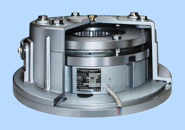
2LM8 spring-operated disk brake
This brake is mounted on 1LA5 and 1LA7 motors in the frame sizes 63 to 225 and on 1LG motors in the frame sizes 180 to 200 as standard.
The 2LM8 brake has IP55 degree of protection.
Please enquire if motors with brakes are to be operated below the freezing point or in very humid environments (e.g. close to the sea) with long standstill times.
Design and mode of operation
The brake takes the form of a single-disk brake with two friction surfaces.
The braking torque is generated by friction when pressure is applied by one or more pressure springs in the de-energized state. The brake is released electromagnetically.
When the motor brakes, the rotor which can be axially shifted on the hub or the shaft is pressed via the armature disk against the friction surface by means of the springs. In the braked state, there is a gap SGap between the armature disk and the solenoid component. To release the brake, the solenoid is energized with DC voltage. The resulting magnetic force pulls the armature disk against the spring force on to the solenoid component. The spring force is then no longer applied to the rotor which can rotate freely.

Design of the 2LM8 spring-operated disk brake
Rating plate
The motors have a second rating plate on the opposite side
to the motor rating plate. The brake data is indicated on this second rating plate
Operating values for spring-operated brakes with standard excitation |
Service capability of the brake | |||||||||||||
|---|---|---|---|---|---|---|---|---|---|---|---|---|---|---|
For motor frame size |
Brake type |
Rated braking |
Rated braking torque in relation to rated braking torque at 100 rpm in % for the following speeds |
Voltage |
Current/power input 1) |
Brake application timet22) |
Brake release time |
Brake moment of inertia |
Noise level Lp with rated air gap |
Lifetime of brake liningL |
Air gap adjustment required after braking energyLN | |||
1500 rpm |
3000 rpm |
Max. speed | ||||||||||||
Nm |
% |
% |
% |
V |
A |
W |
ms |
ms |
kg m2 |
dB (A) |
Nm • 106 |
Nm • 106 | ||
63 |
2LM8 005-1NA10 |
5 |
87 |
80 |
65 |
AC 230 |
0,1 |
20 |
25 |
56 |
0,000013 |
77 |
105 |
16 |
71 |
2LM8 005-2NA10 |
5 |
87 |
80 |
65 |
AC 230 |
0,1 |
20 |
25 |
56 |
0,000013 |
77 |
105 |
16 |
80 |
2LM8 010-3NA10 |
10 |
85 |
78 |
65 |
AC 230 |
0,12 |
25 |
26 |
70 |
0,000045 |
75 |
270 |
29 |
90 |
2LM8 020-4NA10 |
20 |
83 |
76 |
66 |
AC 230 |
0,15 |
32 |
37 |
90 |
0,00016 |
75 |
740 |
79 |
100 |
2LM8 040-5NA10 |
40 |
81 |
74 |
66 |
AC 230 |
0,2 |
40 |
43 |
140 |
0,00036 |
80 |
1350 |
115 |
112 |
2LM8 060-6NA10 |
60 |
80 |
73 |
65 |
AC 230 |
0,25 |
53 |
60 |
210 |
0,00063 |
77 |
1600 |
215 |
132 |
2LM8 100-7NA10 |
100 |
79 |
72 |
65 |
AC 230 |
0,27 |
55 |
50 |
270 |
0,0015 |
77 |
2450 |
325 |
160 |
2LM8 260-8NA10 |
260 |
75 |
68 |
65 |
AC 230 |
0,5 |
100 |
165 |
340 |
0,0073 |
79 |
7300 |
935 |
180 |
2LM8 315-0NA10 |
315 |
75 |
68 |
65 |
AC 230 |
0,5 |
100 |
152 |
410 |
0,0073 |
79 |
5500 |
470 |
200, 225 |
2LM8 400-0NA10 |
400 |
73 |
68 |
65 |
AC 230 |
0,55 |
110 |
230 |
390 |
0,0200 |
93 |
9450 |
1260 |
1) For 400 V AC and for 24 V DC, the power can deviate by up to +10 % as a function of the selected supply voltage.
2) The specified switching times are valid for switching on the DC side with a rated release travel and with the coil already warm. They are average values which may vary depending on factors such as the rectifier type and the release travel. The brake application time for switching on the AC side, for example, is approximately 6 times longer than for switching on the DC side.
Lifetime of the brake lining
The braking energyLN up to when the brake should be adjusted, depends on various factors. The main influencing factors include the masses to be braked, the operating speed, the operating frequency and therefore the temperature at the frictional surfaces. It is therefore not possible to specify a value for the friction energy until readjustment that is valid for all operating conditions.
The specific wear on the friction surfaces (colume of wear per unit of friction energy) is approximately 0.05 to 2 cm3/kWh when the brake is used as a service brake.
Maximum speeds
The maximum speeds from which emergency stops can be made, are listed in the table. These speeds should be considered as recommended values and must be checked under actual operating conditions.
The maximum permissible friction energy depends on the operating frequency and is shown for the various brakes in the figure “Maximum operating energy as a function of the operating frequency”. Increased wear can be expected when the brakes are used for emergency stops.

Maximum speeds |
Changing the braking torque |
Readjusting the air gap | ||||||||
|---|---|---|---|---|---|---|---|---|---|---|
For motor frame size |
Brake type |
Max. operating rpm if max. operating energy utlised |
Max. no-load rpm with emergency stop function |
Reduction per notch |
Dim. “O1” |
Min. braking torque |
Rated air gap |
Max. air gap SGap max. |
Min. rotor thickness hmin. | |
Horizontal mounting |
Vertical |
|||||||||
rpm |
rpm |
rpm |
Nm |
mm |
Nm |
mm |
mm |
mm | ||
63 |
2LM8 005-1NA . . |
3000 |
6000 |
6000 |
0,17 |
7,0 |
3,7 |
0,2 |
0,4 |
4,5 |
71 |
2LM8 005-2NA . . |
3000 |
6000 |
6000 |
0,17 |
7,0 |
3,7 |
0,2 |
0,4 |
4,5 |
80 |
2LM8 010-3NA . . |
3000 |
6000 |
6000 |
0,35 |
8,0 |
7,0 |
0,2 |
0,45 |
5,5 |
90 |
2LM8 020-4NA . . |
3000 |
6000 |
6000 |
0,76 |
7,5 |
18,2 |
0,2 |
0,55 |
7,5 |
100 |
2LM8 040-5NA . . |
3000 |
6000 |
6000 |
1,29 |
12,5 |
21,3 |
0,3 |
0,65 |
8,0 |
112 |
2LM8 060-6NA . . |
3000 |
6000 |
6000 |
1,66 |
11,0 |
32,8 |
0,3 |
0,75 |
7,5 |
132 |
2LM8 100-7NA . . |
3000 |
5300 |
5000 |
1,55 |
13,0 |
61,1 |
0,3 |
0,75 |
8,0 |
160 |
2LM8 260-8NA . . |
1500 |
4400 |
3200 |
5,6 |
17,0 |
157,5 |
0,4 |
1,2 |
12,0 |
180 |
2LM8 315-0NA . . |
1500 |
4400 |
3200 |
5,6 |
17,0 |
178,4 |
0,4 |
1,0 |
12,0 |
200, 225 |
2LM8 400-0NA . . |
1500 |
3000 |
3000 |
6,15 |
21,0 |
248,7 |
0,5 |
1,5 |
15,5 |
Changing the braking torque
The brake is supplied with the braking torque already set. For 2LM8 brakes, the torque can be reduced to the dimension O1 by unscrewing the adjusting ring with a hook spanner. The braking torque changes by the values shown in the above table for each notch of the adjusting ring.
Readjusting the air gap
Under normal operating conditions, the brake is practically maintenance-free. The air gap SGap must only be checked at regular intervals if the application requires an extremely large amount of frictional energy and readjusted to the rated
gap SGap Rated at the latest when the maximum air gap SGap max is reached.

KFB spring-operated brake
This brake is the standard brake for 1LG motors in frame sizes 225 to 315. For frame sizes 180 and 200, apart from the standard brake 2LM8, KFB brakes can also be supplied. Special brake selections are available on request.
KFB spring-operated brake
The KFB solenoid double-disk spring-operated brake is a safety brake which brakes the motor if the supply is disconnected (power failure, emergency stop). The KFB brake, IP65 degree of protection, is mainly used for electric motors for traversing, cross-traversing and lifting gear in cranes as well as for special industrial applications.
Design and mode of operation
When the brake current is switched on, an electromagnetic field develops which overcomes the spring force of the brake. The corresponding modules, including the motor shaft, can rotate freely. The brake is released. If the brake current is switched off or if there is a power failure, the electromagnetic field of the brake disappears. The mechanical braking energy is transferred to the motor shaft. The motor is braked.

Rating plate
The motors have a rating plate that indicates the brake data on the opposite side to the motor rating plate.
Other characteristics of the KFB brake
High IP65 degree of protection
Corrosion-resistant in seawater and in the tropics.
- The brake is a dynamic brake, not simply a holding brake. For this reason there is less wear, especially in the case of emergency stops (commissioning).
- High wear reserves – repeated stepless air gap readjustment is possible. This results in extremely long operating times and low service and operating costs.
- The function and wear can be monitored with microswitches and proximity switches. Microswitch On/Off is standard for LG motors. Anti-condensation heating is possible as an option.
- Fully functional brake for enclosure acceptance test. Visual inspection of brake is possible during operation.
- The brake (air gap) can be adjusted in the factory, for example, and mounted on the motor without further adjustments.
The wear parts can be replaced without great outlay. After the housing has been opened (three screws), it is easy to replace the friction plate. It is not necessary to disassemble the entire brake.
Overview of brake selection for 1LG motors | |||||||
|---|---|---|---|---|---|---|---|
For motor Frame size |
|||||||
180 1) |
200 1) |
225 2) |
250 2) |
280 2) |
315 2) | ||
Number of poles |
2 to 8 |
2 to 8 |
2 to 8 |
2 to 8 |
4 to 8 |
4 to 8 | |
NDE bearing |
6310C3 |
6312C3 |
6313C3 |
6215C3 |
6317C3 |
6319C3 | |
Flange bearing plate for NDE brake mounting |
A300 |
A350 |
A350 |
A400 |
A450 |
A550 | |
Max. diameter for 2nd. shaft extension |
48k6 |
55m6 |
55m6 |
48m6 |
65m6 |
70m6 | |
Braketype |
KFB25 |
KFB40 |
KFB40 |
KFB63 |
KFB100 |
KFB160 | |
Braking torque |
Nm |
250 |
400 |
400 |
630 |
1000 |
1600 |
n maxIMB3 |
rpm |
6000 |
5500 |
5500 |
4700 |
4000 |
3600 |
n maxIMV1 |
rpm |
6000 |
5500 |
5500 |
4700 |
4000 |
3600 |
Output at 110VDC |
W |
158 |
196 |
196 |
220 |
307 |
344 |
Current at 230VAC (207V coil voltage) |
A |
0,77 |
0,91 |
0,91 |
1 |
1,53 |
1,64 |
Current at 400VAC (180V coil voltage) |
A |
0,8 |
1,18 |
1,18 |
1,25 |
1,8 |
2,1 |
Current at 110VDC |
A |
1,44 |
1,78 |
1,78 |
2 |
2,79 |
3,13 |
Current at 24VDC |
A |
5,21 |
6,92 |
9,62 |
8,17 |
12,2 |
12,8 |
Application timet2 |
ms |
70 |
80 |
80 |
110 |
125 |
180 |
Release time |
ms |
240 |
250 |
250 |
340 |
370 |
500 |
Brake moment of inertia |
Kgm2 |
0,0048 |
0,0068 |
0,0068 |
0,0175 |
0,036 |
0,050 |
Lifetime of brake liningL |
Nm · 106 |
3600 |
3110 |
3110 |
4615 |
7375 |
10945 |
Air gap adjustment required after braking energyLN |
Nm · 106 |
810 |
935 |
935 |
1185 |
2330 |
3485 |
1) The standard brake for frame sizes 180 and 200 is the 2LM8 brake.
KFB brake on request
2) The standard brake for frame sizes 225 to 315 is the KFB brake.
Configuration of motors with brakes
Braking time
The time it takes the motor to come to a standstill comprises two components:
a.) The application time of the brake t2
b.) The braking timetBr

tBr Braking time in s
J Total moment of inertia in kgm2
nRated Rated speed of the motor with brake in rpm
T B Rated braking torque in Nm
T
L Average load torque in Nm (ifTL supports braking,
TL is positive)
Braking energy per braking operation Q max
The braking energy per braking operation in Nm comprises the energy of the moments of inertia to be brakedQKin and the energyQL, which must be applied in order to brake against a load torque.
Qmax = QKin + QL
a.) The energy of the moments of inertia in Nm

nRated Rated speed before braking in rpm
J Total moment of inertia in kgm2
b.) The braking energy in Nm against a load torque:

T Laverage load torque in Nm
T L is positive if it acts against the brake
T L is negative if it supports the brake
Run-on revolutions U
The number of run-on revolutionsU of the motor with brake can be calculated as follows:

t 2 Brake application time in ms
Lifetime of the brake lining L and readjustment of the air gap
The brake lining wears due to friction which increases the air gap and the release time for the brake at standard excitation.
When the brake lining is worn out, it can be replaced easily.
In order to calculate the lifetime of the brake lining in terms of operationsSmax, then the lifetime of the brake liningL in Nm must be divided by the braking energyQmax:

The interval between adjustments N in can be calculated in terms of operations by dividing the braking energyLN which the brake can output until it is necessary to readjust the working air gap byQmax:

Additional versions
Depending on the selected motor, brake types 2LM8 or KFB are used.
2LM8 spring-operated disk brake |
KFB spring-operated brake |
|---|---|
Motor series | |
This brake is mounted on 1LA5 and 1LA7 motors in the frame sizes 63 to 225 and on 1LG motors in the frame sizes 180 to 200 as standard. |
This brake is the standard brake for 1LG motors in frame sizes 225 to 315. |
Voltage and frequency | |
The solenoids and the rectifiers of the brakes are designed for connection to the following voltages: 1AC50Hz 230V ±10 % or 1AC60Hz 230V ±10 % When 60Hz is used, the voltage for the brake must not be increased! The brake can also be supplied for other voltages: Brake supply voltage: 24VDC Order codeC00 Brake supply voltage: 400VAC (directly at the terminal strip) Order codeC01 Brake supply voltage: 180V DC, for operation on MM411 ECOFAST (directly at the terminal strip) Order codeC02 Order codesC00,C01 andC02 may only be used in conjunction with order codeG26. |
The solenoids and the rectifiers of the brakes are designed for connection to the following voltages: 1AC50Hz 230V ±10 % When 60Hz is used, the voltage for the brake must not be increased! The brake can also be supplied for other voltages: Brake supply voltage: 24VDC Order codeC00 Brake supply voltage: 400VAC (directly at the terminal strip) Order codeC01 The codesC00 andC01 may only be used in conjunction with CodeG26. |
Connections | |
Labeled terminals are provided in the main connection box of the motor to connect the brake. The AC voltage for the brake excitation winding is connected to the two free terminals of the rectifier block (~). The brake can be released when the motor is at a standstill by separately exciting the solenoid. In this case, an AC voltage must be connected at the rectifier block terminals. The brake remains released as long as this voltage is present. The rectifier is protected against overvoltages by varistors in the input and output circuits. For 24 V DC brakes, the brake terminals are directly connected to the DC voltage source. See the circuit diagrams below. |
The motors are equipped with an additional connection box on the side of the main connection box that is used specifically for connection of the brake. KFB brakes are connected through a standard bridge or half-wave rectifier. See the circuit diagrams below. A spcial circuit is not required. Optimal switching times are achieved without the need to use special circuits.. |
Fast brake application | |
If the brake is disconnected from the line supply, the brake is applied. The application time for the brake disk is delayed as a result of the inductance of the solenoid (shutdown on the AC side). This results in a considerable delay before the brake is mechanically applied. In order to achieve short brake application times, the circuit must be interrupted on the DC side. To realize this, the wire jumpers, located between contacts 1+ and 2+ at the rectifier are removed and replaced by the contact of an external switch (see circuit dia grams below). For 1LG motors with a 2LM8 brake, “Fast application of the brake” is not pos sible in the standard version. Please contact your local Siemens office for advice. |
Not available for the KFB brake. |
Manual brake release with lever | |
The brakes can be supplied with a mechanical manual release with lever. Order codeK82. The dimensions of the brake lever depend on the motor frame size and can be read from the dimension drawing generator for motors in the SD configurator tool for low-voltage motors. |
The brake can be released manually with screws as standard. Mechanical manual release with a lever can be ordered with Order codeK82. The dimensions of the brake lever depend on the motor frame size and can be read from the dimension drawing generator for motors in the SD configurator tool for low-voltage motors. |
Bridge rectifier / half-wave rectifier
Brakes are connected through a standard bridge or half-wave rectifier or directly to the 2LM8 or KFB brake. See the circuit diagrams below.
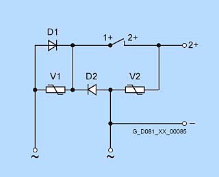
Half-wave rectifier 400 V AC
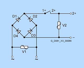
Bridge rectifier, 230 V AC
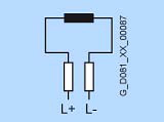
Brake connection for 24 V DC
Combinations of basic versions
The following combinations of modular technology can be supplied by the factory when ordered using the predefined order codes:
Mounting of brake and 1XP8 001 rotary pulse encoder
The brake (order code G26) and the rotary pulse encoder
1XP8 001-1 HTL (order code H57) can be supplied already mounted in combination.
Order codeH62.
The brake (order code G26) and the rotary pulse encoder
1XP8 001-2 TTL (order code H58) can be supplied already mounted in combination.
Order codeH98.
Mounting of separately driven fan and 1XP8 001 rotary pulse encoder
The separately driven fan (order code G17) and the rotary pulse encoder 1XP8 001-1 HTL (order code H57) can be supplied already mounted in combination.
Order codeH61.
The separately driven fan (order code G17) and the rotary pulse encoder 1XP8 001-2 TTL (order code H58) can be supplied already mounted in combination.
Order codeH97.
Mounting of brake and separately-driven fan
The brake (order code G26) and separately driven fan (order code G17) can be supplied already mounted in combination.
Order codeH63.
Mounting of brake, separately driven fan and 1XP8 001 rotary pulse encoder
The brake (order code G26), the separately driven fan (order code G17) and the rotary pulse encoder 1XP8 001-1 HTL (order code H57) can be supplied already mounted in combination.
Order codeH64.
The brake (order code G26), the separately driven fan (order code G17) and the rotary pulse encoder 1XP8 001-2 TTL (order code H58) can be supplied already mounted in combination.
Order codeH99.
When a rotary pulse encoder, brake or separately driven fan is mounted, the length of the motor increases by ? I. For an explanation of the additional dimensions and weights, see “Modular technology”, “Dimensions and weights”.
 Приводная техника