

Bearings and lubrication
Bearing lifetime (nominal lifetime)
The nominal bearing lifetime is defined acc. to standardized calculation procedures (DIN ISO 281) and, for 90 % of the bearings is reached or even exceeded when the motors are operated in the compliance with the data provided in the catalogue.
Under average operating conditions, a lifetime (Lh10) of 100,000 hours can be achieved.
Generally, the bearing lifetime is defined by the bearing size, the bearing load, the operating conditions, the speed and the grease lifetime.
Bearing system
The bearing lifetime of motors with horizontal type of construction is at least 40,000 hours if there is no additional axial loading at the output coupling and at least 20,000 hours with the maximum permitted loads.
This assumes that the motor is operated at 50 Hz. The nominal bearing lifetime is reduced for converter-fed operation at higher frequencies.
For the maximum vibration values measured at the bearing plate, evaluation zones A and B specified in ISO 10816 are applicable in order to achieve the calculated lifetime under continuous duty. If higher vibration speeds will occur under the operating conditions, special arrangements will be necessary (please enquire).
For standard motors applies the following:
In the basic bearing system, the floating bearing is situated at the drive end (DE) and the located bearing (axially located from Type of construction 160 and above) is situated at the non-drive end (NDE). On request, the located bearing can also be supplied at the drive end (DE) (Fig. 3, Page 1/63).
For 1LA8, 1PQ8 and 1LL8 non-standard motors applies the following:
In the basic bearing system, the floating bearing is situated at the non-drive end (NDE) and the located bearing is situated at the drive end (DE).
On request, the located bearing can also be supplied at the non- drive end (NDE).
For ordering all standard and non-standard motors quote
order codeK94.
The bearing system is axially preloaded with a spring element to ensure smooth running of the motor without play.
This is not the case in versions with parallel roller bearings. The bearings of these motors must always run under adequate radial force (motors must not be operated on a testbed without additional radial loads).
Motors of series 1LA6, 1LA7, 1LA9 and 1MA7 up to and including Type of construction 132 have a “floating” bearing arrangement (see Fig. 1, Page 1/63).
Up to Type of construction 132, an additional axially-secured located bearing can be supplied on the non-drive end (NDE) complete with a retaining ring (see Figure 2, Page 1/63).
Order codeL04
For Type of construction 160 and above, bearings are usually axially located (see Figures 2, 4 and 5, Page 1/63).
For increased cantilever forces (e.g. belt drives), reinforced bearings can be used at the drive end (DE).
Order codeK20
Motors 1LG4/6 in Type of constructions 180 to 315, 2-pole, can be supplied with reinforced deep-groove bearings (size range 03).
Special bearings for DE and NDE, bearing size 63
Order codeK36
A measuring nipple for SPM shock pulse measurement is mounted to check bearing vibration. The motors have 1 or 2 tapped holes per bearing plate and a measuring nipple with a protective cap. If a second tapped holes is provided, it is fitted with a sealing cap.
Order codeG50
Bearing arrangement for increased cantilever forces on Pages 1/61 and 1/62 – maximum loading on Pages 1/66 and 1/67.
Insulated bearings
To prevent damage as a result of bearing currents, insulated bearings can be supplied at the non-drive end NDE from Type of construction 225 to 315 and are recommended for Type of construction 225 and above. This bearing design is also possible for 1MJ7 motors from Type of construction 250 to 315.
Order codeL27
The insulated bearing is standard for all 1LA8, 1PQ8 and 1LL8 motors which are identified for converter-fed operation.
Permanent lubrication
For permanent lubrication, the bearing grease lifetime is matched to the bearing lifetime. This can, however, only be achieved if the motor is operated in accordance with the catalogue specifications.
In the basic version, the motors up to and including shaft height 250 have permanent lubrication.
Regreasing
For motors which can be re-greased at defined re-greasing intervals, the bearing lifetime can be extended and/or unfavourable factors such as temperature, mounting conditions, speed, bearing size and mechanical load can be compensated.
From a shaft height of 280 upwards, regreasing with an M10 x 1 flat greasing nipple to DIN 3404 is provided.
It is possible to regrease motors, shaft heights 100 to 250.
A lubricating nipple is optionally provided.
Order codeK40
Mechanical stress and grease lifetime
High speeds that exceed the rated speed with converter-fed operation and the resulting increased vibrations alter the mechanical running smoothness and the bearings are subjected to increased mechanical stress. This reduces the grease lifetime and the bearing lifetime (please enquire where applicable).
For converter-fed operation in particular, compliance with the mechanical limit speedsnmax at maximum supply frequencyfmax is essential, see the section “Motors operating with frequency converters”.
Grease lifetime and regreasing intervals for horizontal installation
Permanent lubrication 1) | ||||
|---|---|---|---|---|
Type series |
Type of construction |
Type |
Number of poles |
Grease lifetime up to KT40°C2) |
All |
56 to 250 |
2 to 8 |
20000 h or 40000 h3) | |
Regreasing (basic version) 1) | ||||
Type series |
Type of construction |
Type |
Number of poles |
Regreasing intervalup toKT40°C2) |
1LA6, 1PP6 |
100 to 160 |
. . . . 10 . to . . . . 16 . |
2 to 8 |
8000 h |
1LA5, 1LP5, 1PP5 |
100 to225 |
. . . . 10 . to . . . . 22 . |
2 to 8 |
8000 h |
1LA8 |
315 to 400 |
. . . . 31 . to . . . . 40 . |
2 |
4000 h |
. . . . 31 . to . . . . 40 . |
4 to 8 |
6000 h | ||
450 |
. . . . 45 . |
2 |
3000 h | |
. . . . 45 . |
4 to 8 |
6000 h | ||
1LL8 |
315 |
. . . . 31 . |
2 |
4000 h |
. . . . 31 . |
4 to 8 |
8000 h / 4000 h 4) | ||
355 to 450 |
. . . . 35 . to . . . . 45 . |
2 |
4000 h | |
. . . . 35 . to . . . . 45 . |
4 to 8 |
6000 h / 3000 h 4) | ||
1LG4, 1LP4, 1PP4 |
180 to 280 |
. . . . 18 . to . . . . 28 . |
2 |
4000 h |
4 to 8 |
8000 h | |||
315 |
. . . . 31 |
2 |
3000 h | |
4 to 8 |
6000 h | |||
1MA6 |
100 to 200 |
. . . . 10 . to . . . . 20 . |
2 to 8 |
8000 h |
225 to 280 |
. . . . 22 . to . . . . 28 . |
2 |
4000 h | |
4 to 8 |
8000 h | |||
315 |
. . . . 315 |
2 |
3000 h | |
4 to 8 |
6000 h | |||
1MA7 |
100 to 160 |
. . . . 10 . to . . . . 16 . |
2 to 8 |
8000 h |
1MJ6 |
180 to 200 |
. . . . 18 . to . . . . 20 . |
2 to 8 |
8000 h |
225 to 280 |
. . . . 22 . to . . . . 28 . |
2 |
4000 h | |
4 to 8 |
8000 h | |||
315 |
. . . . 315 |
2 |
4000 h | |
4 |
8000h | |||
6 and 8 |
11000 h 5) | |||
355 to 450 |
. . . . 35 . to . . . . 45 . |
2 and 4 |
2000 h | |
6 and 8 |
4000 h | |||
1) For special uses and special greases, please enquire about grease lifetime and regreasing intervals.
2) If the coolant temperature is increased by 10 K, the grease lifetime and regreasing interval are halved.
3) 40000 h applies for horizontally installed motors without additional axial loads
4) Regreasing interval for IM V1 type of construction.
5) 8000 h applies for motor series 1MJ7.
Bearing selection table for 1LA5, 1LA6, 1LA7, 1LA9, 1LG, 1LP, 1MA and 1PP motors – basic version
The bearing selection tables are only intended for planning purposes. Authoritative information on the actual type of bearings fitted in motors already supplied can be obtained by the factory by quoting the serial number or can be read from the lubrication plate on 1LA8 motors.
When deep-groove ball bearings with sideplates are used, the side plate is on the inside. For located bearings on drive end DE for 1LA5, 1LA7, 1LA9, 1MA6 and 1MA7 motors, see special version in Figure 3 (Page 1/63).
For motors |
Type of construction Type |
Number of poles Drive end |
(DE) bearing Non-drive end |
NDE bearing Figures |
on Pages | ||
|---|---|---|---|---|---|---|---|
Horizontal type of construction |
Vertical type of construction |
Horizontal type of construction |
Vertical type of construction | ||||
1LA5 . . ., 1LA6 . . ., 1LA7 . . ., 1LA9 . . ., 1LP5 . . ., 1LP7 . . ., | |||||||
56 M |
. . . . 05 . |
2 to 8 |
62012ZC3 |
62012ZC3 |
62012ZC3 |
62012ZC3 |
Fig. 1 |
63 M |
. . . . 06 . |
2 to 8 |
62012ZC3 |
62012ZC3 |
62012ZC3 |
62012ZC3 | |
71 M |
. . . . 07 . |
2 to 8 |
62022ZC3 |
62022ZC3 |
62022ZC3 |
62022ZC3 | |
80 M |
. . . . 08 . |
2 to 8 |
60042ZC3 |
60042ZC3 |
60042ZC3 |
60042ZC3 | |
90 S/L |
. . . . 09 . |
2 to 8 |
62052ZC3 |
62052ZC3 |
60042ZC3 |
60042ZC3 | |
100 L |
. . . . 10 . |
2 to 8 |
62062ZC3 1) |
62062ZC3 1) |
62052ZC3 1) |
62052ZC3 1) | |
112 M |
. . . . 11 . |
2 to 8 |
62062ZC3 1) |
62062ZC3 1) |
62052ZC3 1) |
62052ZC3 1) | |
132 S/M |
. . . . 13 . |
2 to 8 |
62082ZC3 1) |
62082ZC3 1) |
62082ZC3 1) |
62082ZC3 1) | |
160 M/L |
. . . . 16 . |
2 to 8 |
62092ZC3 1) |
62092ZC3 1) |
62092ZC3 1) |
62092ZC3 1) |
Fig. 2 |
180 M/L |
. . . . 18 . |
2 to 8 |
6210ZC3 2) |
6210ZC3 2) |
6210ZC3 2) |
6210ZC3 2) |
Fig. 4 |
200 L |
. . . . 20 . |
2 to 8 |
6212ZC3 2) |
6212ZC3 2) |
6212ZC3 2) |
6212ZC3 2) | |
225 S/M |
. . . . 22 . |
2 to 8 |
6213ZC3 2) |
6213ZC3 2) |
6212ZC3 2)3) |
6212ZC3 2)3) | |
250 M |
. . . . 25 . |
2 to 8 |
6215ZC3 2) |
6215ZC3 2) |
6215ZC3 2) |
6215ZC3 2) | |
280 S/M |
. . . . 28 . |
2 |
6216C3 |
6216C3 |
6216C3 |
6216C3 |
Fig. 5 |
315 S/M |
. . . . 310 . . . . 313 |
2 |
6217C3 |
6217C3 |
6217C3 |
6217C3 | |
315 L |
. . . . 316 . . . . 317 . . . . 318 |
2 |
6217C3 |
6217C3 |
6217C3 |
7217BEP | |
1LG4 . . ., 1LG6 . . ., 1LP4 . . ., | |||||||
180 M/L |
. . . . 18 . |
2 to 8 |
6210ZC3 4) |
6210ZC3 4) |
6210ZC3 4) |
6210ZC3 4) |
Fig. 4 |
200 L |
. . . . 20 . |
2 to 8 |
6212ZC3 4) |
6212ZC3 4) |
6212ZC3 4) |
6212ZC3 4) | |
225 S/M |
. . . . 22 . |
2 to 8 |
6213ZC3 4) |
6213ZC3 4) |
6213ZC3 4) |
6213ZC3 4) | |
250 M |
. . . . 25 . |
2 to 8 |
6215ZC3 4) |
6215ZC3 4) |
6215ZC3 4) |
6215ZC3 4) | |
280 S/M |
. . . . 28 . |
2 |
6217C3 |
6217C3 |
6217C3 |
6217C3 |
Fig. 5 |
315 S/M |
. . . . 310 . . . . 313 |
2 |
6219C3 |
6219C3 |
6219C3 |
6219C3 | |
315 L |
. . . . 316 . . . . 317 . . . . 318 |
2 |
6219C3 |
6219C3 5) |
6219C3 |
7219BEP 5) | |
1) Deep-groove bearings are used for regreasable versions (order codeK40).
2) Deep-groove bearings are not used for regreasable versions (order codeK40) of 1MA6 motors of Type of constructions 180 M to 250 M.
3) Deep-groove bearings are not used for regreasable versions (order codeK40).
4) For 1MA6 motors Type of construction 225 S/M bearing 6213 ZC3 at the non-drive end NDE (BS).
5) Only at 50 Hz.
Bearing selection table for 1LA8, 1PQ8 and 1LL8 motors – basic version
For motors |
Type of constructionType |
Number of polesDrive end |
(DE) bearing Non-drive end |
NDE bearing Figures |
on Pages | ||
|---|---|---|---|---|---|---|---|
Horizontal type of construction |
Vertical type of construction |
Horizontal type of construction |
Vertical type of construction | ||||
1LA8 . . ., 1PQ8 . . . | |||||||
315 |
. . . . 31 . |
2 |
6218 C3 |
6218 C3 |
6218 C3 |
6218 C3 |
Fig. 6 and Fig. 7 |
4 to 8 |
6218 C3 |
6218 C3 |
6218 C3 |
6218 C3 | |||
355 |
. . . . 35 . |
2 |
6218 C3 |
7218 B + 6218 C3 |
6218 C3 |
6218 C3 | |
4 to 8 |
6220 C3 |
7220 B + 6220 C3 |
6220 C3 |
6220 C3 | |||
400 |
. . . . 40 . |
2 |
6218 C3 |
7218 B + 6218 C3 |
6218 C3 |
6218 C3 | |
4 to 8 |
6224 C3 |
7224 B + 6224 C3 |
6224 C3 |
6224 C3 | |||
450 |
. . . . 45 . |
2 |
6220 C3 |
7220 B + 6220 C3 |
6220 C3 |
6220 C3 | |
4 to 8 |
6226 C3 |
7226 B + 6226 C3 |
6226 C3 |
6226 C3 | |||
1LL8 . . . | |||||||
315 |
. . . . 31 . |
2 |
6218 C3 |
6218 C3 |
6218 C3 |
6218 C3 |
No figure |
4 to 8 |
6220 C3 |
7220 B + 6220 C3 |
6218 C3 |
6218 C3 | |||
355 |
. . . . 35 . |
2 |
6218 C3 |
6218 C3 |
6218 C3 |
6218 C3 | |
4 to 8 |
6224 C3 |
7224 B + 6224 C3 |
6220 C3 |
6220 C3 | |||
400 |
. . . . 40 . |
2 |
6218 C3 |
6218 C3 |
6218 C3 |
6218 C3 | |
4 to 8 |
6226 C3 |
7226 B + 6226 C3 |
6224 C3 |
6224 C3 | |||
450 |
. . . . 45 . |
2 |
6220 C3 |
6220 C3 |
6220 C3 |
6220 C3 | |
4 to 8 |
6228 C3 |
7228 B + 6226 C3 |
6228 C3 |
6226 C3 | |||
1LA8, 1PQ8 and 1LL8 non-standard motors are transported horizontally. They can be transported vertically at an additional charge on request
Bearing selection table for 1MJ motors – basic version
For motors |
Type of constructionType |
Number of polesDrive end |
(DE) bearing Non-drive end |
NDE bearing |
Figure | ||
|---|---|---|---|---|---|---|---|
Horizontal type of construction |
Vertical type of construction |
Horizontal type of construction |
Vertical type of construction | ||||
71 M |
1MJ6 07 . |
2 to 8 |
6202 ZC3 |
6202 ZC3 |
6202 ZC3 |
6202 ZC3 |
Fig. 8 |
80 M |
1MJ6 08 . |
2 to 8 |
6004 ZC3 |
6004 ZC3 |
6004 ZC3 |
6004 ZC3 | |
90 S/L |
1MJ6 09 . |
2 to 8 |
6205 C3 |
6205 C3 |
6205 C3 |
6205 C3 |
Fig. 9 |
100 L |
1MJ6 10 . |
2 to 8 |
6206 C3 |
6206 C3 |
6206 C3 |
6206 C3 | |
112 M |
1MJ6 11 . |
2 to 8 |
6306 C3 |
6306 C3 |
6306 C3 |
6306 C3 | |
132 S/M |
1MJ6 13 . |
2 to 8 |
6308 C3 |
6308 C3 |
6308 C3 |
6308 C3 |
Fig. 10 |
160 M/L |
1MJ6 16 . |
2 to 8 |
6309 C3 |
6309 C3 |
6309 C3 |
6309 C3 | |
180 M/L |
1MJ6 18 . |
2 to 8 |
6210 C3 |
6210 C3 |
6210 C3 |
6210 C3 |
Fig. 11 |
200 L |
1MJ6 20 . |
2 to 8 |
6212 C3 |
6212 C3 |
6212 C3 |
6212 C3 | |
225 S/M |
1MJ7 22 . |
2 to 8 |
6213 C3 |
6213 C3 |
6213 C3 |
6213 C3 | |
250 M |
1MJ7 25 . |
2 to 8 |
6215 C3 |
6215 C3 |
6215 C3 |
6215 C3 | |
280 S/M |
1MJ7 28 . |
2 to 8 |
NU 216 |
NU 216 |
6216 C3 |
6216 C3 |
Fig. 12 |
315 S/M |
1MJ7 31 . |
2 |
NU 217 |
NU 217 |
6217 C3 |
6217 C3 | |
4 to 8 |
NU 218 |
NU 218 |
6218 C3 |
6218 C3 |
|||
315 |
1MJ1 31 . |
2 |
6316 C3 |
6316 C3 |
6316 C3 |
6316 C3 1) |
No Figure |
4 to 8 |
6219 C3 |
6219 C3 |
6219 C3 |
6219 C3 | |||
355 |
1MJ8 35 . |
2 |
6316 C3 |
6316 C3 |
6316 C3 |
6316 C3 |
Fig. 13 |
4 to 8 |
6320 C3 |
6320 C3 |
6320 C3 |
6320 C3 | |||
355 |
1MJ1 35 . |
2 |
6316 C4 |
6316 C4 |
6316 C4 |
7316 B | |
4 to 8 |
6320 C3 |
6320 C3 |
6320 C3 |
7320 B | |||
400 |
1MJ1 40 . |
2 |
6317 C4 |
6317 C4 |
6317 C4 |
7317 B | |
4 to 8 |
6322 C3 |
6322 C3 |
6322 C3 |
7322 B | |||
450 |
1MJ1 45 . |
2 |
6318 C4 |
6318 C4 |
6318 C4 |
7318 B | |
4 to 8 |
6324 C3 |
6324 C3 |
6324 C3 |
7324 B | |||
1) For the 60 Hz vertical type of construction, the bearing 6316 C4 is used.
Bearing selection table for 1LA5, 1LA6, 1LA7, 1LA9, 1LG, 1LP, 1MA and 1PP motors – Bearings for increased cantilever forces –Order code K20
Please enquire about noise and vibration data.
For NU bearings, in contrast to standard bearings, a minimum cantilever force is required.
The bearing selection tables are only intended for planning purposes. Authoritative information on the actual type of bearings fitted in motors already supplied can be obtained by the factory by quoting the serial number or can be read from the lubrication plate on 1LA8 motors.
When deep-groove ball bearings with sideplates are used, the side plate is on the inside.
1MJ8 motors at 60 Hz on request.
For motors |
Type of constructionType |
Number of polesDrive end |
(DE) bearing Non-drive end |
NDE bearing |
Figure | ||
|---|---|---|---|---|---|---|---|
Horizontal type of construction |
Vertical type of construction |
Horizontal type of construction |
|||||
1LA5 . . ., 1LA6 . . ., 1LA7 . . ., 1LA9 . . ., 1LP5 . . ., 1LP7 . . ., | |||||||
100 L |
. . . . 10 . |
2 to 8 |
6306 ZC3 |
6306 ZC3 |
62052 ZC3 1) |
62052 ZC3 1) |
No figure |
112 M |
. . . . 11 . |
2 to 8 |
6306 ZC3 |
6306 ZC3 |
62052 ZC3 1) |
62052 ZC3 1) | |
132 S/M |
. . . . 13 . |
2 to 8 |
6308 ZC3 |
6308 ZC3 |
62082 ZC3 1) |
62082 ZC3 1) | |
160 M/L |
. . . . 16 . |
2 to 8 |
6309 ZC3 |
6309 ZC3 |
62092 ZC3 1) |
62092 ZC3 1) | |
180 M/L |
. . . . 18 . |
2 to 8 |
6310 ZC3 |
6310 ZC3 |
6210 ZC3 |
6210 ZC3 | |
200 L |
. . . . 20 . |
2 to 8 |
6312 ZC3 |
6312 ZC3 |
6212 ZC3 |
6212 ZC3 | |
225 S/M |
. . . . 22 . |
2 to 8 |
NU 213 E 2)3) |
NU 213 E 2)3) |
6212 ZC3 4) |
6212 ZC3 4) | |
250 M |
. . . . 253 |
2 to 8 |
NU 215 E 2) |
NU 215E 2) |
6215 ZC3 |
6215 ZC3 | |
280 S/M |
. . . . 28 . |
2 |
NU 216 E |
NU 216 E |
6216 C3 |
6216 C3 | |
315 S/M |
. . . . 310 . . . . 313 |
2 |
NU 217 E |
NU 217 E |
6217 C3 |
6217 C3 | |
315 L |
. . . . 316 . . . . 317 . . . . 318 |
2 |
NU 217 E |
– |
6217 C3 |
– | |
1LG4 . . ., 1LG6 . . ., | |||||||
180 M/L |
. . . . 18 . |
2 to 8 |
NU 210 |
NU 210 |
6210 C3 |
6210 C3 |
Fig. 4 |
200 L |
. . . . 20 . |
2 to 8 |
NU 212 |
NU 212 |
6212 C3 |
6212 C3 | |
225 S/M |
. . . . 22 . |
2 to 8 |
NU 213 |
NU 213 |
6213 C3 |
6213 C3 | |
250 M |
. . . . 25 . |
2 to 8 |
NU 215 |
NU 215 |
6215 C3 |
6215 C3 | |
280 S/M |
. . . . 28 . |
2 |
NU 217 NU 317 |
NU 217 NU 317 |
6217 C3 6317 C3 |
6217 C3 6317 C3 |
Fig. 5 |
315 S/M |
. . . . 310 . . . . 313 |
2 |
NU 219 5) |
NU 219 5) |
6219 C3 |
6219 C3 | |
315 L |
. . . . 316 . . . . 317 . . . . 318 |
2 |
NU 219 5) |
NU 219 5) |
6219 C3 |
6219 C3 | |
1) Deep-groove bearings are used for regreasable versions (order codeK40).
2) Deep-groove bearings of size range 03 are also possible (order codeK36).
3) For 1LA5 motors Type of construction 225 S/M bearing 6313 ZC3 at the non-drive end. Bearing 6313 ZC3.
4) For 1MA6 motors Type of construction 225 S/M bearing 6213 ZC3 at the non-drive end.
5) Only at 50 Hz.
Bearing selection table for 1LA8, 1PQ8 and 1LL8 motors – bearings for increased cantilever forces – Order code K20
For motors |
Type of constructionType |
Number of polesDrive end |
(DE) bearing Non-drive end |
NDE bearing |
|||
|---|---|---|---|---|---|---|---|
Horizontal type of construction |
Vertical type of construction |
||||||
1LA8 . . ., | |||||||
315 |
. . . . 31. |
4 to 8 |
NU 320 E |
On request |
6218 C3 |
On request |
No figure |
355 |
. . . . 35. |
4 to 8 |
NU 320 E |
On request |
6220 C3 |
On request | |
Please enquire about noise and vibration data. For NU bearings, in contrast to standard bearings, a minimum cantilever force is required. The bearing selection tables are only intended for planning purposes. Binding statements about the bearings for motors which have already been shipped can be requested. Please specify the serial number.
The motors are transported horizontally; they can be transported vertically at additional cost on request.
Reinforced bearings are available for Type of constructions 400 and 450 as well as IM V1 types of construction as well as for 1LL8 motors on request. Please specify cantilever force and dimension x. Reinforced bearings cannot be supplied for 2-pole motors.
Bearing selection table for 1MJ6 and 1MJ7 motors – Bearings for increased cantilever forces – Order codeK20
For motors |
Type of constructionType |
Number of polesDrive end |
(DE) bearing Non-drive end |
NDE bearing |
|||
|---|---|---|---|---|---|---|---|
Horizontal type of construction |
Vertical type of construction |
||||||
1MJ6 . . . | |||||||
180 M/L |
. . . . 18. |
2 to 8 |
NU 210 |
NU 210 |
6210 ZC3 |
6210 ZC3 |
No figure |
200 L |
. . . . 20. |
2 to 8 |
NU 212 |
NU 212 |
6212 ZC3 |
6212 ZC3 | |
1MJ7 . . . | |||||||
225 M/L |
. . . . 22. |
2 to 8 |
NU 213 |
NU 213 |
6213 C3 |
6213 C3 |
No figure |
250 M |
. . . . 25. |
2 to 8 |
NU 215 |
NU 215 |
6215 C3 |
6215 C3 | |
Bearing selection table for 1LG4, 1LG6, 1LP4 and 1PP4 motors – Deep-groove bearings reinforced at both ends – Order codeK36
For motors |
Type of constructionType |
Number of polesDrive end |
(DE) bearing Non-drive end |
NDE bearing |
||||||
|---|---|---|---|---|---|---|---|---|---|---|
Horizontal type of construction |
Vertical type of construction |
|||||||||
1LG4 . . ., 1LG6 . . ., 1LP4 . . ., 1PP4 . . . | ||||||||||
180 M/L |
. . . . 18. |
2 to 8 |
6310 ZC3 1) |
6310 ZC3 1) |
6310 ZC3 1) |
6310 ZC3 1) |
Fig. 4 | |||
200 L |
. . . . 20. |
2 to 8 |
6312 ZC3 1) |
6312 ZC3 1) |
6312 ZC3 1) |
6312 ZC3 1) | ||||
225 S/M |
. . . . 22. |
2 to 8 |
6313 ZC3 1) |
6313 ZC3 1) |
6313 ZC3 1) |
6313 ZC3 1) | ||||
250 M |
. . . . 25. |
2 to 8 |
6315 ZC3 1) |
6315 ZC3 1) |
6315 ZC3 1) |
6315 ZC3 1) | ||||
280 S/M |
. . . . 28. |
2 |
6317 C3 |
6317 C3 |
6317 C3 |
6317 C3 |
Fig. 5 | |||
315 S/M/L |
. . . . 31. |
2 |
6316 C3 |
6316 C3 |
6316 C3 |
6316 C3 | ||||
1) Deep-groove bearings are not used for regreasable versions (order codeK40).
2) As for basic version.
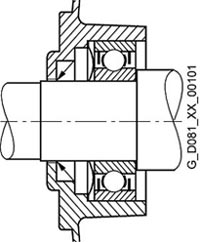
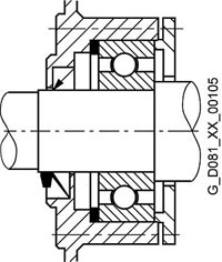
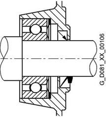
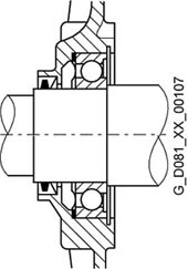
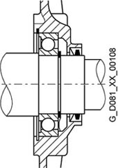
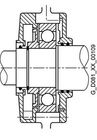
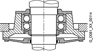
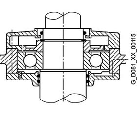
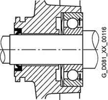
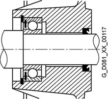
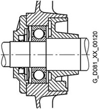
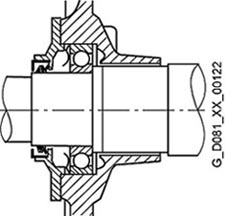
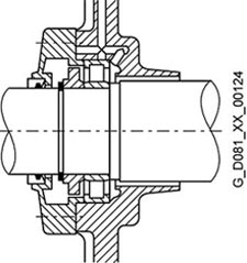
Diagrams of bearings
Fig. 1 |
Drive-end bearing |
Non-drive-end bearing |
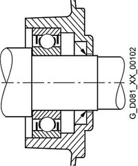
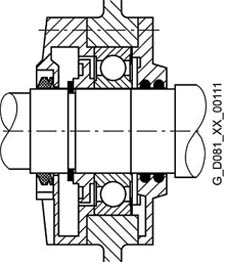
Fig. 2 |
Drive-end bearing |
Non-drive-end bearing |
|---|---|---|---|---|---|
 |
 |
 |
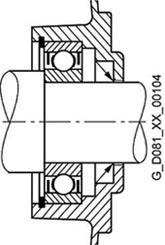 | ||
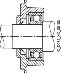
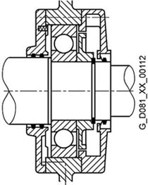
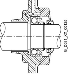
Fig. 3 |
Drive-end bearing |
Non-drive-end bearing |
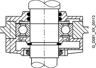
Fig. 4 |
Drive-end bearing |
Non-drive-end bearing |
Location bearing for 1LA7, 1LA9, 1MA7, Type of constructions 56 to 160 |
|||||
 |
 |
 |
 | ||
Location bearing for 1LA5, Type of constructions 180 to 225; 1LA9, 1MA6, Type of constructions 180 to 200 |
|||||
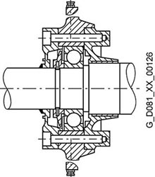
Fig. 5 |
Drive-end bearing |
Non-drive-end bearing |
Fig. 6 |
Drive-end bearing |
Non-drive-end bearing |
 |
 |
 |
 | ||
Type of constructions |
Type of constructions | ||||
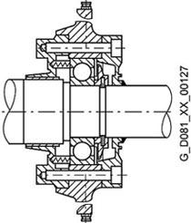
Fig. 7 |
Drive-end bearing |
Drive-end bearing |
Non-drive-end bearing |
||
 |
 |
 |
|||
Type of constructions |
Type of constructions |
Type of constructions |
|||
Fig. 8 |
Drive-end bearing |
Non-drive-end bearing |
Fig. 9 |
Drive-end bearing |
Non-drive-end bearing |
|---|---|---|---|---|---|
 |
 |
 |
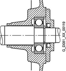 | ||
Fig. 10 |
Drive-end bearing |
Non-drive-end bearing |
Fig. 11 |
Drive-end bearing |
Non-drive-end bearing |
 |
 |
 |
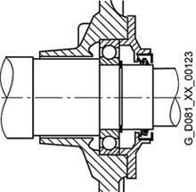 | ||
Fig. 12 |
Drive-end bearing |
Non-drive-end bearing |
Fig. 13 |
Drive-end bearing |
Non-drive-end bearing |
 |
 |
 |
 | ||
Drive-end and non-drive-end bearings |
Maximum cantilever forces
Maximum cantilever forces, basic version

In order to calculate the maximum cantilever forces for a radial load, the line of force (i.e. the centreline of the pulley) of the cantilever forceFQ (N) must lie within the free shaft extension (dimension X).
Dimension x [mm] is the distance between the point of application of forceFQ and the shaft shoulder. Dimension xmax corresponds to the length of the shaft extension.
Total cantilever forceFQ = c · Fu
The pre-tension factor c is a value gained from experience from the belt manufacturer. The following approximate value can be assumed:
For normal flat leather belts with an idler pulleyc = 2;
for V-beltsc = 2 to 2.5;
for special synthetic belts (depending on the type and load)c = 2 to 2.5.
The circumferential force Fu (N) is calculated using the following equation

F ucircumferential force in N
P rated motor power (transmitted power) in kW
n Fan speed in rpm
D pulley diameter in mm
The pulleys are standardized acc. to DIN 2211, Sheet 3.
The maximum cantilever forces at 60 Hz are approx. 80 % of the 50 Hz values (please enquire).
Maximum cantilever forces for the basic 50 Hz version | |||||||
|---|---|---|---|---|---|---|---|
Valid are: x0 values for x = 0 and xmax. values for x = l (l = shaft extension) | |||||||
For motors |
Maximum cantilever force for x0 |
Maximum cantilever force for xmax | |||||
Type of construction |
Numbe r of poles |
Type |
Typ |
||||
N |
N |
N |
N |
N |
N | ||
1LG4 |
1MA6 |
1MJ6 |
1LG4 |
1MA6 |
1MJ6 | ||
250 M |
2 |
3190 |
3650 |
3650 |
2530 |
2950 |
2950 |
4 |
4000 |
4400 |
4400 |
3350 |
3600 |
3600 | |
6 |
4700 |
5350 |
5350 |
3900 |
4350 |
4350 | |
8 |
5200 |
5700 |
5700 |
4400 |
4700 |
4700 | |
280 S |
2 |
4000 |
3350 |
8100 |
3250 |
2800 |
6700 |
4 |
8400 |
8400 |
9700 |
7000 |
7200 |
8050 | |
6 |
9700 |
10000 |
11700 |
8100 |
8900 |
9700 | |
8 |
10750 |
11000 |
12800 |
9000 |
9850 |
10600 | |
315 S |
2 |
4750 |
3950 |
9000 |
3890 |
3350 |
7600 |
4 |
9100 |
9900 |
13100 |
7300 |
8100 |
10800 | |
6 |
10700 |
12100 |
15600 |
8700 |
9900 |
12800 | |
8 |
11600 |
13300 |
16900 |
9600 |
10900 |
13900 | |
315 L |
2 |
4000 |
3100 |
8800 |
3280 |
2700 |
7600 |
4 |
8400 |
8800 |
24000 |
7500 |
7450 |
12000 | |
6 |
9700 |
11400 |
25000 |
9100 |
9600 |
12000 | |
8 |
11100 |
12500 |
26000 |
10200 |
10500 |
12000 | |
1LA5 |
1LG4 |
1MJ6 |
1LA5 |
1LG4 |
1MJ6 | ||
56 M |
2 |
270 |
– |
– |
240 |
– |
– |
4 |
350 |
– |
– |
305 |
– |
– | |
6 |
415 |
– |
– |
360 |
– |
– | |
63 M |
2 |
270 |
– |
– |
240 |
– |
– |
4 |
350 |
– |
– |
305 |
– |
– | |
6 |
415 |
– |
– |
360 |
– |
– | |
71 M |
2 |
415 |
– |
415 |
355 |
– |
355 |
4 |
530 |
– |
530 |
450 |
– |
450 | |
6 |
630 |
– |
630 |
535 |
– |
535 | |
8 |
690 |
– |
– |
585 |
– |
– | |
80 M |
2 |
485 |
– |
485 |
400 |
– |
400 |
4 |
625 |
– |
625 |
515 |
– |
515 | |
6 |
735 |
– |
735 |
605 |
– |
605 | |
8 |
815 |
– |
– |
675 |
– |
675 | |
90 S |
2 |
725 |
– |
725 |
605 |
– |
605 |
4 |
920 |
– |
920 |
775 |
– |
775 | |
6 |
1090 |
– |
1090 |
910 |
– |
910 | |
8 |
1230 |
– |
1230 |
1030 |
– |
1030 | |
100 L |
2 |
1030 |
– |
1030 |
840 |
– |
840 |
4 |
1310 |
– |
1310 |
1060 |
– |
1060 | |
6 |
1550 |
– |
1550 |
1250 |
– |
1250 | |
8 |
1720 |
– |
1720 |
1400 |
– |
1400 | |
112 M |
2 |
1010 |
– |
1680 |
830 |
– |
1490 |
4 |
1270 |
– |
1960 |
1040 |
– |
1580 | |
6 |
1520 |
– |
2140 |
1240 |
– |
1720 | |
8 |
1690 |
– |
2450 |
1380 |
– |
1950 | |
132 S |
2 |
1490 |
– |
2250 |
1180 |
– |
1820 |
4 |
1940 |
– |
2720 |
1530 |
– |
2170 | |
6 |
2260 |
– |
3100 |
1780 |
– |
2420 | |
8 |
2500 |
– |
3400 |
1980 |
– |
2700 | |
160 M |
2 |
1540 |
– |
2800 |
1210 |
– |
2250 |
4 |
2040 |
– |
3330 |
1590 |
– |
2600 | |
6 |
2330 |
– |
3750 |
1820 |
– |
2900 | |
8 |
2660 |
– |
3750 |
2080 |
– |
2900 | |
180 M |
2 |
2000 |
1780 |
2000 |
1550 |
1410 |
1550 |
4 |
2350 |
2240 |
2350 |
1950 |
1820 |
1950 | |
6 |
2800 |
2550 |
2800 |
2250 |
2120 |
2250 | |
8 |
3050 |
2860 |
3050 |
2500 |
2330 |
2500 | |
200 L |
2 |
2550 |
2380 |
2550 |
2100 |
1930 |
2100 |
4 |
3350 |
3050 |
3350 |
2750 |
2530 |
2750 | |
6 |
3900 |
3500 |
3900 |
3200 |
2930 |
3200 | |
8 |
4150 |
3800 |
4150 |
3450 |
3210 |
3450 | |
225 S |
2 |
3050 |
2820 |
3050 |
2550 |
2290 |
2550 |
4 |
3750 |
3500 |
3750 |
2950 |
2760 |
2950 | |
6 |
4550 |
4050 |
4550 |
3600 |
3240 |
3600 | |
8 |
4850 |
4500 |
4850 |
3900 |
3500 |
3900 | |
Table continues overleaf
Maximum cantilever forces for the basic 50 Hz version | |||||||
|---|---|---|---|---|---|---|---|
Valid are: x0 values for x = 0 and xmax. values for x = l (l = shaft extension) | |||||||
For motors |
Maximum cantilever force for x0 |
Maximum cantilever force for xmax | |||||
Type of construction |
Number of poles |
Type |
Type |
||||
N |
N |
||||||
1LA8, 1PQ8, 1MJ8 1) |
1LA8, 1PQ8, 1MJ8 1) | ||||||
315 |
2 ... 8 |
see Diagrams Page 1/68 |
see Diagrams Page 1/68 | ||||
1MJ1 2) |
1MJ1 2) |
||||||
N |
N |
||||||
315 S |
2 |
6200 |
5400 |
||||
4 |
6800 |
5800 |
|||||
6 |
7700 |
6700 |
|||||
8 |
8700 |
7500 |
|||||
315 L |
2 |
5900 |
5300 |
||||
4 |
6200 |
5700 |
|||||
6 |
7000 |
6300 |
|||||
8 |
8000 |
7200 |
|||||
1) Data for 1LL8 is available on request
2) Data for 1MJ1 Type of constructions 355 to 450 will be available soon.
For 1LA8 motors in horizontal type of construction, the maximum cantilever forces are specified with regard to the axial forces.
It should be observed that for types of construction IM B6, IM B7, IM B8, IM V5 and IM V6 the belt tension is only permitted to act parallel to the mounting plane or towards the mounting plane and the feet must be supported. Both feet must be secured for foot-mounting types of construction.
Refer to pages 1/66 to 1/69 if the cantilever forces are higher than those listed above.
Bearing design for increased cantilever forces
Maximum cantilever forces at 50 Hz for 1LA, 1MA, 1MJ, 1LP and | ||||
|---|---|---|---|---|
Deep-groove ball bearings at the drive end (DE) – Order code K20 | ||||
For motors |
Maximum cantilever forceFQ | |||
Type of construction |
Type |
Number of poles |
at x0 |
at xmax. |
N |
N | |||
1LA5 . . ., 1LA6 . . ., 1LA7 . . ., 1LA9 . . ., | ||||
100 |
. . . . 10 . |
2 |
1680 |
1490 |
4 |
1960 |
1580 | ||
6 |
2140 |
1720 | ||
8 |
2450 |
1950 | ||
112 |
. . . . 113 |
2 |
1680 |
1490 |
4 |
1960 |
1580 | ||
6 |
2140 |
1720 | ||
8 |
2450 |
1950 | ||
132 |
. . . . 13 . |
2 |
2250 |
1820 |
4 |
2720 |
2170 | ||
6 |
3100 |
2420 | ||
8 |
3400 |
2700 | ||
160 |
. . . . 16 . |
2 |
2800 |
2250 |
4 |
3330 |
2600 | ||
6 |
3750 |
2900 | ||
8 |
3750 |
2900 | ||
180 |
. . . . 18 . |
2 |
3700 |
3000 |
4 |
4450 |
3600 | ||
6 |
5100 |
4150 | ||
8 |
5550 |
4500 | ||
200 |
. . . . 20 . |
2 |
5200 |
4300 |
4 |
6450 |
5350 | ||
6 |
7300 |
6100 | ||
8 |
7900 |
6550 | ||
225 |
1LA522 . |
2 |
5200 |
4300 |
4 |
6450 |
5350 | ||
6 |
7300 |
6100 | ||
8 |
7900 |
6550 | ||
Maximum cantilever forces at 50 Hz for 1LG-Motoren | ||||
|---|---|---|---|---|
Deep-groove ball bearings at the drive end (DE) – Order code K20 | ||||
Valid are: x0 values for x = 0 and xmax. values for x = l (l = shaft extension) | ||||
For motors |
Maximum cantilever forceFQ | |||
Type of construction |
Type |
Number of poles |
at x0 |
at xmax. |
N |
N | |||
1LG4 . . ., 1LG6 . . ., | ||||
180 M, |
. . . . 18 . |
2 |
4550 |
3600 |
4 |
5650 |
4050 | ||
6 |
6350 |
4050 | ||
8 |
6950 |
4050 | ||
200 L |
. . . . 20 . |
2 |
6600 |
5350 |
4 |
8200 |
6850 | ||
6 |
9300 |
6300 | ||
8 |
10100 |
7400 | ||
225 S, |
. . . . 22 . |
2 |
7500 |
6250 |
4 |
9150 |
7200 | ||
6 |
10400 |
7400 | ||
8 |
11300 |
7350 | ||
250 M |
. . . . 25 . |
2 |
9100 |
7300 |
4 |
11300 |
9300 | ||
6 |
12800 |
10500 | ||
8 |
14100 |
10500 | ||
280 S 1), |
. . . . 28 . |
2 |
11400 |
9350 |
315 S 1), |
. . . . 310 |
2 |
14700 |
12300 |
315 L 1) |
. . . . 316 |
2 |
14600 |
12700 |
1) Not applicable to 1MJ motors with frame sizes 280 to 315, because this is the standard version.
Maximum cantilever forces at 50 Hz for 1MA- und 1MJ-Motoren | ||||
|---|---|---|---|---|
Deep-groove ball bearings at the drive end (DE) – Order code K20 | ||||
For motors |
Maximum cantilever force FQ | |||
Type of construction |
Type |
Numbe rof poles |
at x0 |
at xmax. |
N |
N | |||
1MA6 . . . | ||||
225 |
. . . . 22 . |
2 |
8100 |
6800 |
4 |
9800 |
7800 | ||
6 |
11200 |
8800 | ||
8 |
12200 |
9700 | ||
250 |
. . . . 25 . |
2 |
9600 |
7900 |
4 |
11600 |
9600 | ||
6 |
13200 |
10800 | ||
8 |
14400 |
11800 | ||
280 1)2) |
. . . . 28 . |
2 |
10000 |
8400 |
315 S 1)2) |
. . . . 310 |
2 |
12000 |
10200 |
315 M 1)2) |
. . . . 313 |
|||
315 L 1)2) |
. . . . 316 |
2 |
11800 |
10200 |
. . . . 317 |
(waagerechte Type of construction) | |||
1LA8 |
||||
315 to 355 |
2 to 8 |
siehe Diagramme Seite 1/69 | ||
1) Maximum cantilever forces for 1LG4, 1LG6, 1LP4, 1PP4 and 1MA6 Type of constructions 280 to 315 L in 4-pole to 8-pole version, see Page 1/69.
2) Not applicable to 1MJ motors with Type of constructions 280 to 315, because this is the standard version.
It should be observed that for types of construction IM B6, IM B7, IM B8, IM V5 and IM V6 the belt tension is only permitted to act parallel to the mounting plane or towards the mounting plane and the feet must be supported.
Maximum cantilever forces at 50 Hz for 1LG-Motoren | ||||
|---|---|---|---|---|
Deep-groove bearings reinforced at both ends DE/NDE – Order code K36 | ||||
Valid are: x0 values for x = 0 and xmax. values for x = l (l = shaft extension) | ||||
For motors |
Maximum cantilever forceFQ | |||
Type of constructions |
Type |
Number of poles |
at x0 |
at xmax |
N |
N | |||
1LG4 . . . |
. | |||
180 M, |
. . . . 18 . |
2 |
3280 |
2600 |
4 |
4150 |
3430 | ||
6 |
4750 |
3950 | ||
8 |
5250 |
4050 | ||
200 L |
. . . . 20 . |
2 |
4350 |
3500 |
4 |
5550 |
4550 | ||
6 |
6350 |
5350 | ||
8 |
7000 |
5900 | ||
225 S, |
. . . . 22 . |
2 |
4850 |
3950 |
4 |
6100 |
4850 | ||
6 |
7050 |
5650 | ||
8 |
7750 |
6150 | ||
250 M |
. . . . 25 . |
2 |
5800 |
4600 |
4 |
7400 |
6050 | ||
6 |
8500 |
7050 | ||
8 |
9350 |
7850 | ||
280 S, |
. . . . 28 . |
2 |
– |
– |
315 S, |
. . . . 310 |
2 |
5650 |
4650 |
315 L |
. . . . 316 |
2 |
5450 |
4650 |
Maximum cantilever forces at 50 Hz for 1LA8- and 1PQ8 motors – basic version
Type of construction 315, 1LA8 und 1PQ8 – Type of construction IM B3 |
Frame size 355, 1LA8 und 1PQ8 – Type of construction IM B3 |
|---|---|
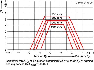 |
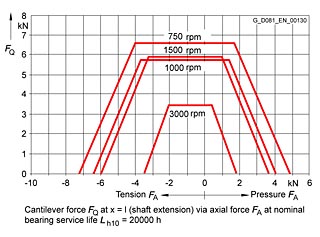 |
Frame size 400, 1LA8 und 1PQ8 – Type of construction IM B3 |
Frame size 450, 1LA8 und 1PQ8 – Type of construction IM B3 |
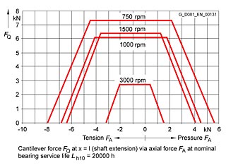 |
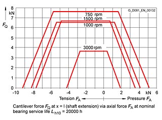 |
Maximum cantilever forces at 50 Hz for 1LA8- and 1PQ8 motors – Bearings for increased cantilever forces – Order codeK20
Frame size 355, 1MJ8 |
|
|---|---|
 |
Maximum cantilever forces at 50 Hz for 1LA8- and 1PQ8 motors – Bearings for increased cantilever forces – Order codeK20
Frame size 315, 1LA8 und 1PQ8 – Type of construction IM B3 |
Frame size 355, 1LA8 und 1PQ8 – Type of construction IM B3 |
|---|---|
 |
 |
At 60 Hz, the maximum cantilever force must be reduced to 80 %.
For all motors of frame sizes 400 and 450, IM V1 and 1LL8 motors with reinforced bearings available on request.
Please specify cantilever force and lever arm.
Maximum cantilever forces at 50 Hz for 1LG4 motors – Bearings for increased cantilever forces – Order codeK20
Frame size 280, 4- to 8-pole, 1LG4/1LG6, 1LP4/1PP4 |
Frame size 315, 4- to 8-pole, 1LG4/1LG6, 1LP4/1PP4 |
Frame size 315 S/M, 4- to 8-pole, 1LG4/1LG6, 1LP4/1PP4 |
|---|---|---|
 |
 |
 |
Maximum cantilever forces at 50 Hz for 1MA motors – Bearings for increased cantilever forces – Order codeK20
Frame size 280, 4- to 8-pole, 1MA6 |
Frame size 315 S/M, 4- to 8-pole, 1MA6 |
Frame size 315 L, 4- to 8-pole, 1MA6 |
|---|---|---|
 |
 |
 |
Maximum axial load
1LA5, 1LA6, 1LA7, 1LP5, 1LP7, 1MA6, 1MA7, 1MJ1, 1MJ6, 1MJ7, 1MJ8, 1PP5, 1PP6, 1PP7 motors in vertical
type of construction – basic version
Frame size |
Shaft extension pointing | |||||||||||||||
|---|---|---|---|---|---|---|---|---|---|---|---|---|---|---|---|---|
3000 rpm |
1500 rpm |
1000 rpm |
750 rpm | |||||||||||||
downwards |
upwards |
downwards |
upwards |
downwards |
upwards |
downwards |
upwards | |||||||||
Load down |
Load down |
Load down |
Load down |
Load down |
Load down |
Load down |
Load down | |||||||||
nach |
nach |
nach |
nach |
nach |
nach |
nach |
nach |
nach |
nach |
nach |
nach |
nach |
nach |
nach |
nach | |
N |
N |
N |
N |
N |
N |
N |
N |
N |
N |
N |
N |
N |
N |
N |
N | |
56 |
80 |
245 |
230 |
95 |
80 |
330 |
310 |
95 |
80 |
410 |
390 |
95 |
– |
– |
– |
– |
63 |
80 |
245 |
230 |
95 |
80 |
330 |
310 |
95 |
80 |
410 |
390 |
95 |
– |
– |
– |
– |
71 |
105 |
365 |
335 |
130 |
90 |
380 |
440 |
130 |
90 |
590 |
550 |
130 |
90 |
700 |
660 |
130 |
80 |
110 |
425 |
360 |
160 |
100 |
540 |
480 |
165 |
100 |
650 |
590 |
165 |
100 |
760 |
700 |
165 |
90 |
110 |
440 |
360 |
180 |
100 |
680 |
580 |
190 |
100 |
920 |
820 |
190 |
100 |
1150 |
1050 |
190 |
100 |
140 |
700 |
550 |
280 |
130 |
990 |
820 |
285 |
130 |
1280 |
1110 |
285 |
130 |
1560 |
1390 |
285 |
112 |
140 |
710 |
550 |
300 |
130 |
1000 |
820 |
310 |
130 |
1290 |
1110 |
310 |
130 |
1570 |
1390 |
310 |
(140)* |
(1050)* |
(800)* |
(300)* |
(130)* |
(1350)* |
(1100)* |
(300)* |
(130)* |
(1720)* |
(1500)* |
(310)* |
(130)* |
(2000)* |
(1850)* |
(310)* | |
132 |
200 |
1200 |
950 |
470 |
180 |
1680 |
1200 |
470 |
180 |
1900 |
1600 |
470 |
190 |
2200 |
1900 |
440 |
(1500)* |
(1550)* |
(1300)* |
(470)* |
(1500)* |
(2100)* |
(1600)* |
(470)* |
(280)* |
(2400)* |
(2100)* |
(470)* |
(290)* |
(2800)* |
(2400)* |
(440)* | |
160 |
1500 |
1400 |
950 |
1900 |
1900 |
1800 |
1300 |
2200 |
2200 |
2200 |
1600 |
2700 |
2700 |
2700 |
1950 |
2900 |
(2000)* |
(1720)* |
(1300)* |
(2500)* |
(2500)* |
(2400)* |
(1720)* |
(2800)* |
(2800)* |
(2800)* |
(2130)* |
(3600)* |
(3600)* |
(3600)* |
(2600)* |
(3700)* | |
* The values in brackets for frame sizes 112 to 160 apply to 1MJ6 motors.
Fur Motoren |
Shaft extension downwards | ||||||||||||||||
|---|---|---|---|---|---|---|---|---|---|---|---|---|---|---|---|---|---|
Frame size |
3000 rpm |
1500 rpm |
1000 rpm |
750 rpm | |||||||||||||
Loaddown |
Load up |
Loaddown |
Load up |
Loaddown |
Load up |
Loaddown |
Load up | ||||||||||
Typ |
1LA5... |
1MJ6.. |
1LA5... |
1MJ6... |
1LA5... |
1MJ6... |
1LA5... |
1MJ6... |
1LA5... |
1MJ6... |
1LA5... |
1MJ6... |
1LA5... |
1MJ6... |
1LA5... |
1MJ6... | |
1LA5 . . . 1MA6 . . . 1MJ6 . . . 1MJ7 . . . 1LP5 . . . 1PP5 . . . |
1MA6 1LP5 1PP5 |
1MJ7 |
1MA6 1LP5 1PP5 |
1MJ7 |
1MA6 1LP5 1PP5 |
1MJ7 |
1MA6 1LP5 1PP5 |
1MJ7 |
1MA6 1LP5 1PP5 |
1MJ7 |
1MA6 1LP5 1PP5 |
1MJ7 |
1MA6 1LP5 1PP5 |
1MJ7 |
1MA6 1LP5 1PP5 |
1MJ7 | |
N |
N |
N |
N |
N |
N |
N |
N |
N |
N |
N |
N |
N |
N |
N |
N | ||
180 M |
. . . . 183 |
1150 |
1150 |
1900 |
1900 |
1400 |
1400 |
2350 |
2350 |
– |
– |
– |
– |
– |
– |
– |
– |
180 L |
. . . . 186 |
– |
– |
– |
– |
1400 |
1400 |
2400 |
2400 |
1700 |
1700 |
2850 |
2850 |
2000 |
2000 |
3150 |
3150 |
200 L |
. . . . 206 |
1650 |
1650 |
2750 |
2750 |
– |
– |
– |
– |
2550 |
2550 |
3950 |
3950 |
– |
– |
– |
– |
. . . . 207 |
1550 |
1550 |
2800 |
2800 |
2000 |
2000 |
3350 |
3350 |
2400 |
2400 |
3950 |
3950 |
2800 |
2800 |
4500 |
4500 | |
225 S |
. . . . 220 |
– |
– |
– |
– |
2300 |
2300 |
3020 |
3020 |
– |
– |
– |
– |
3200 |
3200 |
4080 |
4080 |
225 M |
. . . . 223 |
1890 |
1890 |
2190 |
2190 |
2180 |
2180 |
3060 |
3060 |
2700 |
2700 |
3500 |
3500 |
3040 |
3040 |
4120 |
4120 |
250 M |
. . . . 253 |
1750 |
1750 |
2790 |
2790 |
2160 |
2160 |
3760 |
3760 |
2740 |
2740 |
4340 |
4340 |
2990 |
2990 |
4890 |
4890 |
280 S |
. . . . 280 |
380 |
1150 |
4480 |
3850 |
3830 |
1350 |
8790 |
4950 |
5340 |
2350 |
10000 |
5650 |
6280 |
2850 |
11000 |
6250 |
280 M |
. . . . 283 |
180 |
900 |
4580 |
3900 |
3550 |
1000 |
8910 |
5000 |
5000 |
2000 |
10100 |
5700 |
5930 |
2450 |
11100 |
6300 |
315 S |
. . . . 310 |
210 |
900 |
5270 |
4500 |
3700 |
1700 |
10200 |
6400 |
5150 |
2300 |
11700 |
7050 |
6520 |
3400 |
13000 |
7950 |
315 M |
. . . . 313 |
100 |
650 |
5350 |
4550 |
3330 |
1600 |
10400 |
6900 |
4740 |
2050 |
11700 |
7500 |
5800 |
2800 |
13000 |
8400 |
315 L |
. . . . 316 |
9270 |
– |
770 |
– |
2330 |
– |
10400 |
– |
3650 |
– |
11700 |
– |
4630 |
– |
13000 |
– |
. . . . 317 |
9270 |
– |
840 |
– |
1370 |
– |
10800 |
– |
2990 |
– |
11600 |
– |
3760 |
– |
13000 |
– | |
. . . . 318 |
9270 |
– |
840 |
– |
1370 |
– |
10800 |
– |
2990 |
– |
11600 |
– |
3760 |
– |
13000 |
– | |
The values shown do not assume a cantilever force on the shaft extension.
The maximum loads are valid for operation at 50 Hz; for 60 Hz, please enquire.
The calculation of the maximum axial load was based on the drive with generally available coupling. For suppliers, see the relevant section of the catalogue “Accessories and spare parts”.
Please enquire regarding 1MJ8 and 1MJ1 motors.
Please enquire if the load direction alternates.
1LA5, 1LA6, 1LA7, 1LP7, 1MA6, 1MA7, 1MJ1, 1MJ6, 1MJ7, 1MJ8, 1PP6, 1PP7 motors in horizontal type of construction – Basic version
Frame size |
3000 rpm |
1500 rpm |
1000 rpm |
750 rpm | ||||||||||||
|---|---|---|---|---|---|---|---|---|---|---|---|---|---|---|---|---|
Tensile |
Thrust load (N) |
Tensile |
Thrust load (N) |
Tensile |
Thrust load (N) |
Tensile |
Thrust load (N) | |||||||||
with radial load at |
without radial load |
with radial load at |
without radial load |
with radial load at |
without radial load |
with radial load at |
without radial load | |||||||||
x0 |
xmax. |
x0 |
xmax. |
x0 |
xmax. |
x0 |
xmax. |
|||||||||
N |
N |
N |
N |
N |
N |
N |
N |
N |
N |
N |
N |
N |
N |
N |
N | |
56 |
90 |
120 |
90 |
240 |
90 |
140 |
110 |
320 |
90 |
170 |
120 |
400 |
– |
– |
– |
– |
63 |
90 |
120 |
90 |
240 |
90 |
140 |
110 |
320 |
90 |
170 |
120 |
400 |
– |
– |
– |
– |
71 |
120 |
150 |
120 |
350 |
120 |
210 |
150 |
460 |
120 |
260 |
180 |
570 |
120 |
300 |
210 |
680 |
80 |
140 |
190 |
150 |
400 |
140 |
300 |
260 |
510 |
140 |
330 |
280 |
620 |
140 |
340 |
290 |
730 |
90 |
150 |
300 |
280 |
400 |
150 |
400 |
360 |
630 |
150 |
480 |
430 |
870 |
150 |
550 |
500 |
1100 |
100 |
220 |
450 |
350 |
630 |
220 |
600 |
500 |
910 |
220 |
650 |
550 |
1200 |
220 |
750 |
650 |
1480 |
112 |
220 |
450 |
350 |
630 |
220 |
600 |
500 |
910 |
220 |
650 |
550 |
1200 |
220 |
750 |
650 |
1480 |
(220)* |
(850)* |
(700)* |
(1050)* |
(220)* |
(1150)* |
(1000)* |
(1350)* |
(220)* |
(1300)* |
(1150)* |
(1720)* |
(220)* |
(1450)* |
(1300)* |
(2000)* | |
132 |
350 |
650 |
520 |
1200 |
350 |
850 |
700 |
1600 |
350 |
1020 |
890 |
1900 |
350 |
1150 |
1020 |
2200 |
(350)* |
(1000)* |
(900)* |
(1550)* |
(350)* |
(1250)* |
(1150)* |
(2100)* |
(350)* |
(1500)* |
(1400)* |
(2400)* |
(350)* |
(1750)* |
(1650)* |
(2800)* | |
160 |
1500 |
850 |
720 |
1500 |
1500 |
1050 |
920 |
1800 |
1500 |
1250 |
1120 |
2200 |
1500 |
1350 |
1220 |
2600 |
(2100)* |
(1280)* |
(1100)* |
(2100)* |
(2100)* |
(1680)* |
(1700)* |
(2350)* |
(2100)* |
(2050)* |
(1920)* |
(2900)* |
(2100)* |
(2400)* |
(2200)* |
(3300)* | |
* Die Werte in Klammern fur die Type of constructions 112 to 160 gelten fur 1MJ6-Motoren und fur die Type of constructions 280 S to 315 M fur 1MJ7-Motoren.
For motors |
3000 rpm |
1500 rpm |
1000 rpm |
750 rpm |
|||||
|---|---|---|---|---|---|---|---|---|---|
Loading direction |
Loading direction |
Loading direction |
Loading direction | ||||||
Frame size |
Type |
Tension |
Thrust |
Tension |
Thrust |
Tension |
Thrust |
Tension |
Thrust |
1LA5 . . . 1MA6 . . . 1MJ6 . . . 1MJ7 . . . 1LP5 . . . 1PP5 . . . |
|||||||||
N |
N |
N |
N |
N |
N |
N |
N | ||
180 M |
. . . . 183 |
1400 |
1400 |
1700 |
1700 |
– |
– |
– |
– |
180 L |
. . . . 186 |
– |
– |
1700 |
1700 |
2050 |
2050 |
2400 |
2400 |
200 L |
. . . . 206 |
2000 |
2000 |
– |
– |
3000 |
3000 |
– |
– |
. . . . 207 |
1950 |
1950 |
2450 |
2450 |
2900 |
2900 |
3400 |
3400 | |
225 S |
. . . . 220 |
2980 |
1960 |
3880 |
2860 | ||||
225 M |
. . . . 223 |
2390 |
1370 |
2900 |
1880 |
3380 |
2360 |
3810 |
2790 |
250 M |
. . . . 253 |
2450 |
1655 |
3070 |
2270 |
3620 |
2820 |
4000 |
3200 |
280 S |
. . . . 280 |
1330(3700)* |
2900(2100)* |
5080(4200)* |
6740(2600)* |
6410(5000)* |
8070(3400)* |
7390(5550)* |
9050(3950)* |
280 M |
. . . . 283 |
1200(3600)* |
2800(2000)* |
4990(4000)* |
6650(2400)* |
6260(4800)* |
7920(3200)* |
7220(5350)* |
8880(3750)* |
315 S |
. . . . 310 |
1500(3800)* |
3160(2200)* |
5350(4900)* |
7450(3300)* |
6740(5500)* |
8810(3900)* |
8010(6500)* |
10110(4900)* |
315 M |
. . . . 313 |
1400(3650)* |
3180(2050)* |
5260(4900)* |
7360(3300)* |
6560(5450)* |
8660(3850)* |
7690(6250)* |
9790(4650)* |
315 L |
. . . . 316 |
1080 |
2740 |
4580 |
6680 |
5770 |
7870 |
6820 |
8920 |
. . . . 317 |
940 |
2600 |
4170 |
6270 |
5410 |
7510 |
6410 |
8510 | |
. . . . 318 |
940 |
2600 |
4170 |
6270 |
5410 |
7510 |
6410 |
8510 | |
* The values in brackets for frame sizes 112 to 160 apply to 1MJ6 motors and frame sizes 280 S to 315 M apply to 1MJ7 motors.
The values shown do not assume a cantilever force on the shaft extension.
The maximum loads are valid for operation at 50 Hz; for 60 Hz, please enquire.
The calculation of the maximum axial load was based on the drive with generally available coupling. For suppliers, see the relevant section of the catalogue “Accessories and spare parts”.
Please enquire regarding 1MJ8 and 1MJ1 motors.
Please enquire if the load direction alternates.
1LG4, 1LG6, 1LP4, 1PP4 and 1PP6 motors in vertical type of construction – Basic version
For motors | |||||||||
|---|---|---|---|---|---|---|---|---|---|
Frame size |
Type |
3000 rpm |
1500 rpm |
1000 rpm |
750 rpm | ||||
1LG4 . . . 1LG6 . . . 1LP4 . . . 1PP4 . . . 1PP6 . . . |
Load down |
Load up |
Load down |
Load up |
Load down |
Load up |
Load down |
Load up | |
N |
N |
N |
N |
N |
N |
N |
N | ||
Shaft extension downwards | |||||||||
180 M |
. . . . 183 |
1140 |
1150 |
1500 |
1600 |
– |
– |
– |
– |
180 L |
. . . . 186 |
– |
– |
1380 |
1630 |
1650 |
2000 |
2020 |
2250 |
. . . . 188 |
1140 |
1190 |
1390 |
1650 |
1640 |
2030 |
1880 |
2280 | |
200 L |
. . . . 206 |
1610 |
1480 |
– |
– |
2420 |
2550 |
– |
– |
. . . . 207 |
1510 |
1530 |
2030 |
2100 |
2220 |
2610 |
2610 |
2970 | |
. . . . 208 |
1510 |
1590 |
1990 |
2120 |
2210 |
2680 |
2600 |
3060 | |
225 S |
. . . . 220 |
– |
– |
2110 |
2690 |
– |
– |
2830 |
3710 |
225 M |
. . . . 223 |
1540 |
1990 |
1920 |
2770 |
2260 |
3300 |
2620 |
3770 |
. . . . 228 |
1540 |
2070 |
1950 |
2840 |
2240 |
3430 |
2610 |
3880 | |
250 M |
. . . . 253 |
1680 |
2760 |
2110 |
3740 |
2740 |
4350 |
3070 |
4920 |
. . . . 258 |
1660 |
2870 |
2110 |
3960 |
2740 |
4520 |
3070 |
5160 | |
280 S |
. . . . 280 |
390 |
4670 |
3190 |
8200 |
4510 |
9290 |
5510 |
10300 |
280 M |
. . . . 283 |
100 |
4780 |
2790 |
8340 |
4210 |
9450 |
5200 |
10400 |
. . . . 288 |
100 |
4950 |
2700 |
8570 |
4170 |
9600 |
5160 |
10600 | |
315 S |
. . . . 310 |
840 |
6330 |
3380 |
10200 |
4760 |
11500 |
5860 |
12600 |
315 M |
. . . . 313 |
530 |
6490 |
2870 |
10500 |
4200 |
11800 |
5420 |
12900 |
315 L |
. . . . 316 |
8830 |
590 |
2450 |
11000 |
3680 |
12300 |
4800 |
13400 |
. . . . 317 |
8410 |
690 |
1800 |
11400 |
3100 |
12800 |
4410 |
13900 | |
. . . . 318 |
8170 |
800 |
1620 |
12000 |
2690 |
13400 |
3820 |
14300 | |
Shaft extension upwards | |||||||||
180 M |
. . . . 183 |
1900 |
390 |
2260 |
840 |
– |
– |
– |
– |
180 L |
. . . . 186 |
– |
– |
2140 |
870 |
2410 |
1240 |
2780 |
1490 |
. . . . 188 |
1900 |
430 |
2150 |
890 |
2400 |
1270 |
2640 |
1520 | |
200 L |
. . . . 206 |
2760 |
330 |
– |
– |
3570 |
1400 |
– |
– |
. . . . 207 |
2660 |
380 |
3180 |
950 |
3370 |
1460 |
3760 |
1820 | |
. . . . 208 |
2660 |
440 |
3140 |
970 |
3360 |
1530 |
3750 |
1910 | |
225 S |
. . . . 220 |
– |
– |
3130 |
1670 |
– |
– |
3850 |
2690 |
225 M |
. . . . 223 |
2560 |
970 |
2940 |
1750 |
3280 |
2280 |
3640 |
2750 |
. . . . 228 |
2560 |
1050 |
2970 |
1820 |
3260 |
2410 |
3630 |
2860 | |
250 M |
. . . . 253 |
2480 |
1960 |
2910 |
2940 |
3540 |
3550 |
3870 |
4120 |
. . . . 258 |
2460 |
2070 |
2910 |
3160 |
3540 |
3720 |
3870 |
4360 | |
280 S |
. . . . 280 |
1960 |
3100 |
4760 |
6630 |
6080 |
7720 |
7080 |
8730 |
280 M |
. . . . 283 |
1670 |
3210 |
4360 |
6770 |
5780 |
7880 |
6770 |
8830 |
. . . . 288 |
1670 |
3380 |
4270 |
7000 |
5740 |
8030 |
6730 |
9030 | |
315 S |
. . . . 310 |
2410 |
4760 |
5380 |
8200 |
6760 |
9500 |
7860 |
10600 |
315 M |
. . . . 313 |
2100 |
4920 |
4870 |
8500 |
6200 |
9800 |
7420 |
10900 |
315 L |
. . . . 316 |
10400 |
– |
4450 |
9000 |
5680 |
10300 |
6800 |
11400 |
. . . . 317 |
9980 |
– |
3800 |
9400 |
5100 |
10800 |
6410 |
11900 | |
. . . . 318 |
9740 |
– |
3620 |
10000 |
4690 |
11400 |
5820 |
12300 | |
Values shown without assuming a cantilever force on the shaft extension.
The maximum loads apply to operation at 50 Hz; please enquire about 60 Hz.
The figures for the maximum axial loads have been calculated assuming that standard coupling types are used for the drive. For suppliers, see the relevant section of the catalogue “Accessories and spare parts”.
Please enquire if the loading direction alternates.
1LG4, 1LG6, 1LP4, 1PP4 and 1PP6 motors in horizontal type of construction – Basic version
For motors |
3000 rpm |
1500 rpm |
1000 rpm |
750 rpm | |||||
|---|---|---|---|---|---|---|---|---|---|
Frame size |
Type |
Loading direction |
Loading direction |
Loading direction |
Loading direction | ||||
1LG4 . . . 1LG6 . . . 1LP4 . . . 1PP4 . . . 1PP6 . . . |
Tension |
Thrust |
Tension |
Thrust |
Tension |
Thrust |
Tension |
Thrust | |
N |
N |
N |
N |
N |
N |
N |
N | ||
180 M |
. . . . 183 |
1550 |
790 |
1950 |
1190 |
– |
– |
– |
– |
180 L |
. . . . 186 |
– |
– |
1890 |
1130 |
2220 |
1460 |
2470 |
1710 |
. . . . 188 |
1550 |
790 |
1900 |
1140 |
2220 |
1460 |
2460 |
1700 | |
200 L |
. . . . 206 |
2150 |
990 |
– |
– |
3090 |
1940 |
– |
– |
. . . . 207 |
2130 |
970 |
2670 |
1520 |
3030 |
1880 |
3410 |
2260 | |
. . . . 208 |
2130 |
970 |
2630 |
1480 |
3020 |
1870 |
3410 |
2250 | |
225 S |
. . . . 220 |
– |
– |
2950 |
1920 |
– |
– |
3820 |
2790 |
225 M |
. . . . 223 |
2320 |
1290 |
2910 |
1880 |
3360 |
2330 |
3760 |
2740 |
. . . . 228 |
2320 |
1290 |
2910 |
1880 |
3350 |
2320 |
3760 |
2730 | |
250 M |
. . . . 253 |
2510 |
1710 |
3150 |
2350 |
3750 |
2950 |
4180 |
3380 |
. . . . 258 |
2510 |
1710 |
3140 |
2340 |
3750 |
2950 |
4170 |
3370 | |
280 S |
. . . . 280 |
1790 |
3360 |
4970 |
6540 |
6180 |
7750 |
7170 |
8740 |
280 M |
. . . . 283 |
1720 |
3290 |
4860 |
6430 |
6110 |
7680 |
7090 |
8660 |
. . . . 288 |
1720 |
3290 |
4850 |
6420 |
6100 |
7670 |
7080 |
8650 | |
315 S |
. . . . 310 |
2610 |
4180 |
5520 |
7520 |
6830 |
8830 |
7940 |
9940 |
315 M |
. . . . 313 |
2500 |
4070 |
5320 |
7320 |
6520 |
8520 |
7850 |
9850 |
315 L |
. . . . 316 |
2450 |
4020 |
5230 |
7230 |
6370 |
8370 |
7520 |
9520 |
. . . . 317 |
2320 |
3890 |
5050 |
7050 |
6110 |
8110 |
7350 |
9350 | |
. . . . 318 |
2300 |
3870 |
4950 |
6950 |
5950 |
7950 |
7080 |
9080 | |
1LA8 and 1PQ8 motors in vertical type of construction – Basic version
For motors |
Shaft end facing downwards | ||||||||
|---|---|---|---|---|---|---|---|---|---|
Frame size |
3000 rpm |
1500 rpm |
1000 rpm |
750 rpm | |||||
Type |
Load down |
Load up |
Load down |
Load up |
Load down |
Load up |
Load down |
Load up | |
1LA8 . . . 1PQ8 . . . 1LL8 . . . |
|||||||||
N |
N |
N |
N |
N |
N |
N |
N | ||
315 |
. . . . 315 |
1900 |
5240 |
2790 |
6930 |
3060 |
8600 |
3850 |
9390 |
. . . . 317 |
1440 |
5680 |
2280 |
7420 |
2390 |
9230 |
3190 |
10030 | |
355 |
. . . . 353 |
8480 |
5570 |
14550 |
7900 |
– |
– |
– |
– |
. . . . 355 |
8180 |
5860 |
14200 |
8240 |
15690 |
10650 |
17840 |
11650 | |
. . . . 357 |
7530 |
6500 |
13400 |
9030 |
14540 |
11780 |
16690 |
12780 | |
400 |
. . . . 403 |
6780 |
7260 |
17640 |
11160 |
19500 |
14160 |
22260 |
15330 |
. . . . 405 |
6330 |
7700 |
17040 |
11750 |
18750 |
14910 |
21510 |
16070 | |
. . . . 407 |
5930 |
8100 |
16340 |
12440 |
17900 |
15750 |
20660 |
16910 | |
450 |
. . . . 453 |
5330 |
9650 |
17720 |
13020 |
19950 |
16250 |
23040 |
17550 |
. . . . 455 |
4730 |
10250 |
17020 |
13720 |
19050 |
17140 |
22140 |
18440 | |
. . . . 457 |
4130 |
10840 |
16270 |
14460 |
18000 |
18180 |
21090 |
19480 | |
For 1LA8 and 1PQ8 motors in a horizontal type of construction, the maximum cantilever forces are specified with regard to the axial forces, see Page /.
Data is available for 1LL8 motors on request.
Values shown without assuming a cantilever force on the shaft extension.
The maximum loads apply to operation at 50 Hz; please enquire about 60 Hz.
The figures for the maximum axial loads have been calculated assuming that standard coupling types are used for the drive. For suppliers, see the relevant section of the catalogue “Accessories and spare parts”.
Please enquire if the loading direction alternates.
 Приводная техника