Siemens
01 2018
(4872) 700-366
skenergo@mail.ru

Reliable functioning of analyzers is of decisive importance for process control. It is necessary to record, correct and transmit measured values, to set and modify parameters, to check functions, to update calibrations, and to scan status signals e.g. for preventive maintenance. Communication between the operator and device is therefore an important part of process analysis, and the offered facilities have become a decisive performance feature of analyzers.

Extractive continuous process gas analysis

The gas analyzers of Series 6 (ULTRAMAT 6, ULTRAMAT/OXYMAT 6, OXYMAT 6, OXYMAT 61, OXYMAT 64, FIDAMAT 6, CALOMAT 6, CALOMAT62) as well as the ULTRAMAT 23 offer the following communication options in addition to data transmission with analog and digital outputs:

  • RS 485 interface
  • SIPROMGA
  • PROFIBUSDP/PA
  • Generic communications interface (only OXYMAT6, ULTRAMAT6 and ULTRAMAT/OXYMAT6).

The modular SIPROCESSGA700 gas analyzer with the ULTRAMAT 7, OXYMAT7 and CALOMAT7 modules offers the following communication options in addition to data transmission with analog and digital outputs:

  • MODBUSTCP
  • Remote transmission via UMTS router
  • ModbusTCP/PROFINET communication

RS485 interface

The serial interface integrated as standard permits communication between several analyzers over the internal bus (ELAN). Parameterization is carried out using the analyzer's menu.

Networking over ELAN

ELAN communication is used e.g. for the interference gas correction of interfering gases. Direct connection is only possible between Siemens gas analyzers.

Bus cable with plug connections, ELAN networking

Specification for the interface cable

Surge impedance

100 ... 300 Ω, with a measuring frequency of > 100kHz

Cable capacitance

Typ. < 60pF/m

Core cross-section

> 0.22mm2, corresponds to AWG 23

Cable type

Twisted pair, 1 x 2 conductors of cable section

Signal attenuation

Max. 9dB over the whole length

Shielding

Copper braided shield or braided shield and foil shield

Connection

Pin 3 and pin 8


  • Bus terminating resistors
    Pins 3-7 and 8-9 of the first connector of a bus cable must be bridged (ELAN networking).

Note

If the cable is longer than 500m or high interference effects are present, it is advisable to install a repeater on the device side.

Networking with SIPROMGA

When used externally, the RS-485 interface requires software matched to the analyzers, e.g. SIPROM GA.

SIPROMGA is a software program for communication between a PC or laptop and analyzers. A maximum of 12 devices (electronics modules) with up to four channels/measured components of the following type can be connected, displayed and remote-controlled per COM interface:

  • OXYMAT6/61
  • OXYMAT 64
  • ULTRAMAT6
  • CALOMAT6
  • CALOMAT 62
  • FIDAMAT6
  • ULTRAMAT 23

SIPROMGA allows access to device parameters all the way to the device configuration. All analyzer functions (except factory default functions) can be remote-controlled and monitored in this manner. SIPROMGA is therefore an ideal service and maintenance tool for Siemens gas analyzers.

In addition to remote control of all operator functions, SIPROMGA offers full access to all diagnostic data. SIPROMGA therefore permits preventive maintenance as well as fast responses when maintenance becomes necessary or when the production process is changed.

SIPROMGA guarantees:

  • High operational reliability
  • High availability
  • Central, comprehensive information
  • Fast response time
  • Flexibility
  • Economical system integration

In addition to the display of analyzers with TAG No., components, current measured values, comprehensive diagnostics information (status) and parameter assignment, SIPROM GA also offers the following possibilities:

  • Bargraph display
  • Recorder display of one or more measured values with printer output
  • Calibration functions (adjustment of all setpoints for calibration, remote calibration)
  • Saving of all device data
  • Remote control of all device functions
  • Remote calibration
  • Online help
  • Downloading of new device firmware
  • Cyclic saving of measured values on hard disk
  • Writing user data to the device's EEPROM, or downloading data from it.

Analyzers are accessed using SIPROMGA in one of the following two ways:

  • Directly from the PC with an RS485 interface
  • Via an Ethernet gateway

Hardware requirements

In order to use SIPROMGA, the following hardware and system requirements for the PC/laptop equipment must be met:

  • Windows computer with Pentium 133MHz and 32MB RAM:
    Recommendation: Pentium II 266MHz and 64MB RAM
  • CD-ROM drive (for installation)
  • Free hard disk capacity of at least 10MB
  • VGA graphics card (Windows-supported);
    resolution: 1024 x 768
  • Printer (Windows-supported)
  • MS Windows 95, ME; NT 4, Windows 98, Windows 2000, Windows XP, or Windows7 operating system
  • Vacant COM port (COM 1, 2 ...)
    • The RS485/ RS232 interface converter is required for the connection to the RS485 ELAN network
    • A standard 10Mbit or 100 Mbit network (RJ45 connection) with TCP/ IP is required for connection of the Ethernet/ RS485 interface converter

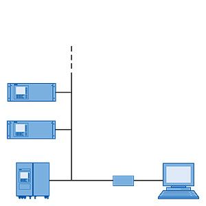
Accessories for the network

For cables, connectors, repeaters etc., see Catalog IK PI or in the Mall in CA 01 under SIMATIC NET communications systems / PROFIBUS / Network components.

Networking with SIPROMGA via converter

A maximum of 12 analyzers with up to four components each can be networked.

The functional principle is shown in the following illustration.

Typical structure of an RS485 Ethernet network via SIPROMGA

The gas analyzers can be installed at distances up to 500m. One network can be connected to each COM port.

Networking with SIPROMGA via Ethernet

For access via Ethernet, there are no limitations on the distance between PC and gateway. In addition, communication via Ethernet enables the installation of multiple gateways on one COM port. As a result, the possibility exists for operator control and monitoring of multiple analyzers or analyzer systems located far away and far apart from one station.

Typical structure of an RS485 Ethernet network via SIPROMGA

PROFIBUS

The commonly used practice of transmitting measured values and fault messages via analog and digital outputs requires complex cabling. By contrast, with PROFIBUS DP and PROFIBUS PA, a single 2-wire cable is possible for digital transmission of, for example, all measured values (including from several channels), status information and diagnostics functions for preventive maintenance.

The PROFIBUS DP version is widely used in production automation because of its high transmission rate for relatively small data quantities per device. PROFIBUS PA makes allowance, in particular, for the properties required in process industry, e.g. large data quantities and use in hazardous areas.

The limited dynamic performance of 4to 20mA mA signals can be replaced, the laborious configuring of measuring ranges can be omitted. By using simulated measured values without media, increased safety can be provided for the plant configuration, and configuration errors can be avoided. Parameter sets can be generated offline (from your desk) and subsequently downloaded and saved in the device. Local operations can thus be reduced to a minimum.

With an optional plug-in card, which can also be retrofitted, the following Siemens gas analyzers are PROFIBUS-compatible and comply with the mandatory "Device profile for analyzers" of the PI (PROFIBUS International).

  • OXYMAT6/61
  • OXYMAT 64
  • ULTRAMAT 23
  • ULTRAMAT6
  • CALOMAT6
  • CALOMAT 62
  • FIDAMAT6

Customer benefits include enormous savings potential in all plant areas, covering configuration and commissioning, operation and maintenance, up to subsequent plant expansions.

Operation of the gas analyzers from a control system or a separate PC is possible with the SIMATIC PDM tool (Process Device Manager). The SIMATICPDM software runs on Windows and can be integrated in the SIMATICPCS7 process control system. This permits a clear presentation for integration of the analyzers in the system as well as for the complex parameter structure of the analyzers.

Direct connection of the analyzers to a control system without PDM, e.g. using STEP 7, is also possible but this requires additional programming and is less convenient for the operator. In most cases, this direct connection is therefore only applicable if acyclic (device operation) data are not used.

A differentiation is made between cyclic and acyclic services. Cyclic services are used to transmit time-critical data such as measured values and statuses. The acyclic services allow device parameters to be queried or changed during operation.

Both graphic displays and values can be output on a PC. Signaling of maintenance, fault and diagnostics information is also cyclic. These data are displayed in plain text when using SIMATICPDM.

The digital outputs can also be switched using cyclic services, thus also permitting triggering of relays over PROFIBUS (e.g. for measuring point switchover, calibration etc.).

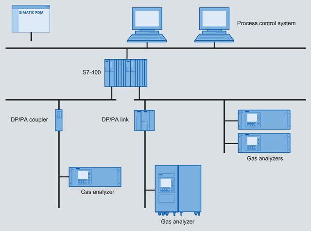
Schematic structure of a PROFIBUS system

The following acyclic device parameters and device configurations can be used in PROFIBUSDP and PROFIBUSPA with SIMATIC PDM:

  • Factory data
  • Diagnostics values
  • Logbook
  • Display measuring ranges
  • Zero calibration
  • Sensitivity calibration
  • Zero point/sensitivity setpoints
  • Total/single calibration and AUTOCAL
  • Select measuring ranges
  • Define measuring ranges
  • Electrical time constants
  • On/off functions
  • Chopper frequency
  • Magnetic field frequency
  • Date/time
  • Measuring point switchover
  • Logbook settings
  • Relay assignment
  • Digital inputs
  • Reset
  • Save/load data
  • Suppression of short noise signals
  • Calibration tolerances
  • Switch valves
  • PROFIBUS configuration

Use of PROFIBUS offers the following customer benefits:

  • Cost reductions for planning, installation and operation
  • Use of (distributed) device intelligence
  • Replaceability of devices
  • Only one cable for everything, no complex cabling
  • No limited 4to 20mA resolution
  • No laborious parameterization of measuring ranges
  • Simulation of measured values
  • Simplification of commissioning
  • Testing of network/AS
  • Avoidance of errors during startup
  • Online diagnostics
  • Offline parameterization

Generic communications interface
(only OXYMAT6, ULTRAMAT6 and ULTRAMAT/OXYMAT6)

Users benefit from numerous functions that are mainly needed in the automotive industry, for example, to carry out repeated linearization. In contrast to PROFIBUS and ELAN, communication is only possible between one device and one PC, and takes place according to the master/slave principle. The device only transmits data when requested by a command telegram, where only one command can be processed and replied to at a time.

Function88 can be used to open the generic communications menu and set the parameters.

SIPROCESSGA700: connection via ModbusTCP

Der SIPROCESS GA700 uses ModbusTCP for interference gas corrections and for external pressures for measured value processing. Measured values such as process value, pressure and temperature can also be imported from other SIPROCESS‑GA700‐devices and shown on the display.

The SIPROCESSGA700 can simultaneously accept up to seven connections via ModbusTCP.
Modbus TCP function codes 3, 16 and 43 are currently supported:

  • Current measured values such as process value, pressure, temperature and device status can be determined with function code3.
  • Device identification data are made available using function code43.
  • The eight virtual Modbus digital inputs can be written with function code16.

The virtual digital inputs can be freely configured just like the physical inputs. As a result for example, it is possible to start an AutoCAL, set external errors and switch between various measuring ranges via ModbusTCP.

SIPROCESSGA700: Possible communication paths

The SIPROCESSGA700 has two Ethernet interfaces: one process interface and one service interface.
While the device is connected to the plant bus, device parameters can be assigned in parallel via the service interface.

  • The process and service interfaces are interconnected (switch functionality).
  • There is no limit on the number of SIPROCESSGA700 devices in an Ethernet network.
  • The device parameters are assigned using SIMATICPDM (Ethernet).
  • The SIPROCESSGA700 can be connected to a controller via ModbusTCP.
    An additional Modbuslibrary is needed for SIMATICPCS7 (SIMATICS7‑400).
    A standard block (SIMATICPCS7 SIMATICS7‑400: MonAna/MonAnl) is used to acquire and display the values. As a result, the data is also available in WinCC.

The parameter assignment using SIMATICPDM is also possible via a point-to-point connection with the SIPROCESSGA700.

Close-distance and long-distance remote access to the SIPROCESSGA700 can also be set up using standard network components (WLAN access point / UMTS router / DSL router). The following figure shows a selection of possible communication paths and network components that the SIPROCESSGA700 can use for communication.

SIPROCESSGA700: Communication paths and network components

With a ModbusTCP/PROFINET gateway, the SIPROCESSGA700 can also be connected to a controller via PROFINET.

Connection of two separate networks (e.g. multiple locations) via the Internet.

A VPN tunnel is set up over the Internet between a UMTS router (plant environment) and an ADSL router (office environment). All SIPROCESSGA700 devices can now be addressed from any node using, for example, SIMATICPDM/controller/Modbus client in one of the two networks via ModbusTCP and S7-400 (PDM).

Remote access

The WLANaccesspoint enables mobile access to devices via a laptop, for example. If a PDM web server was installed and set up, you can access the SIPROCESSGA700 devices from hand-held devices (mobile phone, tablet) via a web browser. The PDM web server is a computer on which SIMATIC PDM with additional web server functionalities is installed.

In-situ continuous process gas analysis

LDS6 can send and receive data over an Ethernet connection with the help of the LDScom software. This installation and service tool is able to check and adapt device status and calibration parameters from a remote location. If necessary, even a complete system check can be carried out over the remote connection. If servicing is necessary, the required information can be sent to the Siemens service engineer by router, and he can then carry out the appropriate measures from the remote location.

This facility for remote maintenance and diagnostics is implemented using a standard LAN modem.

External connection of LDS6 via a modem for implementing remote maintenance measures


skener.ru

Deprecated: Function eregi() is deprecated in /home/h101150-2/siemens71.ru/docs/kip/kip.php on line 23

Deprecated: Function eregi() is deprecated in /home/h101150-2/siemens71.ru/docs/kip/kip.php on line 23

Deprecated: Function eregi() is deprecated in /home/h101150-2/siemens71.ru/docs/kip/kip.php on line 30

Deprecated: Function eregi() is deprecated in /home/h101150-2/siemens71.ru/docs/kip/kip.php on line 30

Deprecated: Function eregi() is deprecated in /home/h101150-2/siemens71.ru/docs/kip/kip.php on line 30


Deprecated: Function eregi() is deprecated in /home/h101150-2/siemens71.ru/docs/kip/kip.php on line 30

Deprecated: Function eregi() is deprecated in /home/h101150-2/siemens71.ru/docs/kip/kip.php on line 30
DENDOR

Deprecated: Function eregi() is deprecated in /home/h101150-2/siemens71.ru/docs/kip/kip.php on line 23

Deprecated: Function eregi() is deprecated in /home/h101150-2/siemens71.ru/docs/kip/kip.php on line 30

Deprecated: Function eregi() is deprecated in /home/h101150-2/siemens71.ru/docs/kip/kip.php on line 30

Deprecated: Function eregi() is deprecated in /home/h101150-2/siemens71.ru/docs/kip/kip.php on line 30


Deprecated: Function eregi() is deprecated in /home/h101150-2/siemens71.ru/docs/kip/kip.php on line 30

Deprecated: Function eregi() is deprecated in /home/h101150-2/siemens71.ru/docs/kip/kip.php on line 30

Deprecated: Function eregi() is deprecated in /home/h101150-2/siemens71.ru/docs/kip/kip.php on line 23

Deprecated: Function eregi() is deprecated in /home/h101150-2/siemens71.ru/docs/kip/kip.php on line 30

Deprecated: Function eregi() is deprecated in /home/h101150-2/siemens71.ru/docs/kip/kip.php on line 30

Deprecated: Function eregi() is deprecated in /home/h101150-2/siemens71.ru/docs/kip/kip.php on line 30

Deprecated: Function eregi() is deprecated in /home/h101150-2/siemens71.ru/docs/kip/kip.php on line 30


Deprecated: Function eregi() is deprecated in /home/h101150-2/siemens71.ru/docs/kip/kip.php on line 30
SKW-FS -

Deprecated: Function eregi() is deprecated in /home/h101150-2/siemens71.ru/docs/kip/kip.php on line 23

Deprecated: Function eregi() is deprecated in /home/h101150-2/siemens71.ru/docs/kip/kip.php on line 30

Deprecated: Function eregi() is deprecated in /home/h101150-2/siemens71.ru/docs/kip/kip.php on line 30

Deprecated: Function eregi() is deprecated in /home/h101150-2/siemens71.ru/docs/kip/kip.php on line 30

Deprecated: Function eregi() is deprecated in /home/h101150-2/siemens71.ru/docs/kip/kip.php on line 30


Deprecated: Function eregi() is deprecated in /home/h101150-2/siemens71.ru/docs/kip/kip.php on line 30
SKW-FK -

  © " " 2007-2022
  (4872) 700-366  skenergo@mail.ru
.