Siemens
СРЕДСТВА ПРОМЫШЛЕННОЙ АВТОМАТИЗАЦИИ
официальный партнер Сименс
Каталог СА01 2018
(4872) 700-366
skenergo@mail.ru

Stabilized DC power supplies have electronic control circuits that maintain the DC voltage at the output at a specific value with as little variation as possible. Effects such as variation in input voltage or changes in load at the output are electrically compensated in the specified function area.

The ripple in the output voltage for stabilized DC power supplies lies in the millivolt range and is mainly dependent on the loading at the outputs.

Stabilized DC power supplies can be implemented on different functional principles. The most common types of circuit are:

  • Linear stabilized power supplies
  • Magnetic voltage stabilizers
  • Secondary pulsed switched-mode power supplies
  • Primary pulsed switched-mode power supplies

The most suitable principle for a particular application case will depend mainly on the application. The objective is to generate a DC voltage to supply the specific load as inexpensively and as accurately as possible.

Power supplies with in-phase regulation

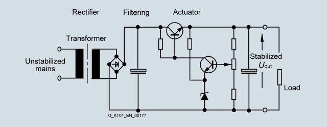
Block diagram Transformer with in-phase regulation

The transformer with in-phase regulation operates according to a conventional principle. The supply is provided from an AC supply system (one, two or three conductor supply).

A transformer is used to adapt it to the required secondary voltage.

The rectified and filtered secondary voltage is converted to a stabilized voltage at the output in a regulation section. The regulation section comprises a final control element and a control amplifier. The difference between the stabilized output voltage and the non-stabilized voltage at the filter capacitor is converted into a thermal loss in the final control element. The final control element functions in this case like a rapidly changeable ohmic impedance. The thermal loss that arises in each case is the product of output current and voltage drop over the final control element.

This system is extremely adaptable. Even without further modifications, several output voltages are possible. In the case of multiple outputs, the individual secondary circuits are usually generated from separate secondary windings of the input transformer. Some applications can only be resolved in accordance with this circuit principle. Especially when highly accurate regulation, minimal residual ripple and fast compensation times are required.

The efficiency is, however, poor and the weight and volume are considerable. The transformer with in-phase regulation is therefore only an economical alternative at low power ratings.

Advantages:

  • Simple, well-proven circuit principle
  • Good to excellent control characteristics
  • Fast compensation time

Disadvantages:

  • Relatively high weight and large construction volume due to the 50 Hz transformer
  • Poor efficiency, heat dissipation problems
  • Low storage time
Magnetic stabilizer

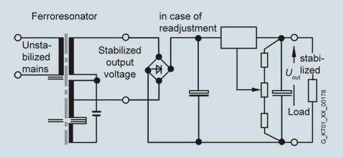
Block diagram Magnetic stabilizer

The complete transformer comprises two components. The "ferro resonator" and a series-connected auxiliary regulator. The input winding and the resonance winding of the magnetic stabilizer are decoupled to a large extent by means of the air gap. The magnetic stabilizer supplies a well-stabilized AC voltage. This is rectified and filtered. The transformer itself is operated in the saturation range.

The ferro resonator frequently has a transformer with in-phase regulation connected downstream to improve the control accuracy. Secondary pulsed switched-mode regulators are frequently also connected downstream.

The magnetic stabilizer technique is reliable and rugged but is also large-volume, heavy and relatively expensive.

Advantages:

  • Good to excellent control characteristics in combination with transformer with in-phase regulation connected downstream
  • Significantly better efficiency than a transformer with in-phase regulation alone

Disadvantages:

  • The ferro resonator is frequency dependent
  • The power supplies are large and heavy due to the magnetic components
Secondary pulsed switched-mode power supplies:

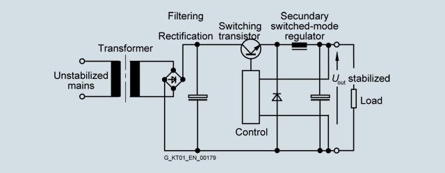
Block diagram Secondary pulsed switched-mode power supplies

Isolation from the supply system is implemented in this case with a 50 Hz transformer. Following rectification and filtering, the energy is switched at the output by means of pulsing through a switching transistor in the filtering and storage circuit. Thanks to the transformer at the input that acts as an excellent filter, the mains pollution is low.
The efficiency of this circuit is extremely high.

This concept offers many advantages for power supplies with numerous different output voltages.

To protect the connected loads, however, care must be taken; in the event of the switching transistor breaking down, the full, non-stabilized DC voltage of the filter capacitor will be applied to the output. However, this danger also exists in the case of linear stabilized power supplies.

Advantages:

  • Simple design and high efficiency
  • Multiple outputs, also galvanically isolated from one another, are easily implemented by means of several secondary windings
  • Fewer problems with interference than with primary pulsed switched-mode power supplies

Disadvantages:

  • The 50 Hz transformer makes the power supplies relatively large and heavy
  • The output ripple (spikes) correspond to those of a primary pulsed switched-mode power supply
Primary pulsed switched-mode power supplies:

The term SMPS (Switch Mode Power Supply) or primary switched-mode regulator is often used in the literature.

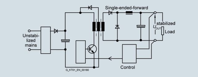
Block diagram Single-ended forward converter

The primary switched-mode regulators are available in many different circuit versions. The most important basic circuits are single-ended forward converters, flyback converters, half-bridge converters, full-bridge converters, push-pull converters and resonance converters.

The general principle of operation of the primary switched-mode regulator is shown in the block diagram of the single-ended forward converter:

The non-stabilized supply voltage is first rectified and filtered. The capacitance of the capacitor in the DC link determines the storage time of the power supply on failure of the input voltage. The voltage at the DC link is approximately 320 V DC for a 230 V supply. A single-ended converter is then supplied with this DC voltage and transfers the primary energy through a transformer to the secondary side with the help of a pulse width regulator at a high switching frequency. The switching transistor has low power losses when functioning as a switch so that the power balance lies between > 70% and at least 90%, depending on the output voltage and current.

The volume of the transformer is small in comparison with a 50 Hz transformer due to the high switching frequency because the transformer size, taking into account the higher switching frequency, is smaller. Using modern semiconductors, clock frequencies of 100 kHz and above can be achieved. However, switching losses increase at excessively high clock frequencies so that in each case a compromise has to be made between high efficiency and the largest possible clock frequency. In most applications, the switching frequencies lie between approximately 20 kHz and 250 kHz depending on the output power.

The voltage from the secondary winding is rectified and filtered. The system deviation at the output is fed back to the primary circuit through an optocoupler. By controlling the pulse width (conducting phase of the switching transistor in the primary circuit), the necessary energy is transferred to the secondary circuit and the output voltage is regulated. During the non-conducting phase of the switching transistor, the transformer is demagnetized through an auxiliary winding. Exactly the same amount of energy is transferred as is removed at the output. The maximum pulse width for the pulse duty factor for these circuits is < 50%.

Advantages:

  • Small magnetic components (transformer, storage reactor, filter) thanks to the high operating frequency
  • High efficiency thanks to pulse width regulation
  • Compact equipment units
  • Forced-air cooling is not necessary up to the kW range
  • High storage times are possible in case of power failure by increasing the capacitance in the DC link
  • Large input voltage range possible

Disadvantages:

  • High circuit costs, many active components
  • High costs for interference suppression
  • The mechanical design must be in accordance with HF criteria

Primary switched-mode power supplies have taken over from the other switching modes in recent years. This is due, in particular, to their compact size, minimal weight, high efficiency and excellent price/performance ratio.

Summary

The most important characteristics of the circuit types described above are summarized in the table.


Connection methods

Comparison criteria

Primary-switched mode

Secondary-switched mode

Transformer with in-phase regulation

Magnetic stabilizer

Input voltage range

Very large

Average

Very small

Large

Regulation speed

Average

Average

Very fast

Slow

Storage time after power failure

Very long

Long

Very short

Long

Residual ripple

Average

Average

Very low

Average

Power loss

Very small

Small

Large

Very small

Size

Very small

Average

Very large

Large

Weight

Very light

Average

Heavy

Very heavy

Interference suppression overhead

Very large

Average

Low

Average


Comparison criteria for basic circuit versions


skener.ru

Deprecated: Function eregi() is deprecated in /home/h101150-2/siemens71.ru/docs/kip/kip.php on line 23

Deprecated: Function eregi() is deprecated in /home/h101150-2/siemens71.ru/docs/kip/kip.php on line 23

Deprecated: Function eregi() is deprecated in /home/h101150-2/siemens71.ru/docs/kip/kip.php on line 30

Deprecated: Function eregi() is deprecated in /home/h101150-2/siemens71.ru/docs/kip/kip.php on line 30

Deprecated: Function eregi() is deprecated in /home/h101150-2/siemens71.ru/docs/kip/kip.php on line 30


Deprecated: Function eregi() is deprecated in /home/h101150-2/siemens71.ru/docs/kip/kip.php on line 30

Deprecated: Function eregi() is deprecated in /home/h101150-2/siemens71.ru/docs/kip/kip.php on line 30
Арматура DENDOR

Deprecated: Function eregi() is deprecated in /home/h101150-2/siemens71.ru/docs/kip/kip.php on line 23

Deprecated: Function eregi() is deprecated in /home/h101150-2/siemens71.ru/docs/kip/kip.php on line 30

Deprecated: Function eregi() is deprecated in /home/h101150-2/siemens71.ru/docs/kip/kip.php on line 30

Deprecated: Function eregi() is deprecated in /home/h101150-2/siemens71.ru/docs/kip/kip.php on line 30


Deprecated: Function eregi() is deprecated in /home/h101150-2/siemens71.ru/docs/kip/kip.php on line 30

Deprecated: Function eregi() is deprecated in /home/h101150-2/siemens71.ru/docs/kip/kip.php on line 30
Датчики и измерители

Deprecated: Function eregi() is deprecated in /home/h101150-2/siemens71.ru/docs/kip/kip.php on line 23

Deprecated: Function eregi() is deprecated in /home/h101150-2/siemens71.ru/docs/kip/kip.php on line 30

Deprecated: Function eregi() is deprecated in /home/h101150-2/siemens71.ru/docs/kip/kip.php on line 30

Deprecated: Function eregi() is deprecated in /home/h101150-2/siemens71.ru/docs/kip/kip.php on line 30


Deprecated: Function eregi() is deprecated in /home/h101150-2/siemens71.ru/docs/kip/kip.php on line 30

Deprecated: Function eregi() is deprecated in /home/h101150-2/siemens71.ru/docs/kip/kip.php on line 30
Регуляторы и регистраторы

Deprecated: Function eregi() is deprecated in /home/h101150-2/siemens71.ru/docs/kip/kip.php on line 23

Deprecated: Function eregi() is deprecated in /home/h101150-2/siemens71.ru/docs/kip/kip.php on line 30

Deprecated: Function eregi() is deprecated in /home/h101150-2/siemens71.ru/docs/kip/kip.php on line 30

Deprecated: Function eregi() is deprecated in /home/h101150-2/siemens71.ru/docs/kip/kip.php on line 30


Deprecated: Function eregi() is deprecated in /home/h101150-2/siemens71.ru/docs/kip/kip.php on line 30

Deprecated: Function eregi() is deprecated in /home/h101150-2/siemens71.ru/docs/kip/kip.php on line 30
Пневматическое оборудование

Deprecated: Function eregi() is deprecated in /home/h101150-2/siemens71.ru/docs/kip/kip.php on line 23

Deprecated: Function eregi() is deprecated in /home/h101150-2/siemens71.ru/docs/kip/kip.php on line 30

Deprecated: Function eregi() is deprecated in /home/h101150-2/siemens71.ru/docs/kip/kip.php on line 30

Deprecated: Function eregi() is deprecated in /home/h101150-2/siemens71.ru/docs/kip/kip.php on line 30


Deprecated: Function eregi() is deprecated in /home/h101150-2/siemens71.ru/docs/kip/kip.php on line 30

Deprecated: Function eregi() is deprecated in /home/h101150-2/siemens71.ru/docs/kip/kip.php on line 30
Краны и Клапаны

Deprecated: Function eregi() is deprecated in /home/h101150-2/siemens71.ru/docs/kip/kip.php on line 23

Deprecated: Function eregi() is deprecated in /home/h101150-2/siemens71.ru/docs/kip/kip.php on line 30

Deprecated: Function eregi() is deprecated in /home/h101150-2/siemens71.ru/docs/kip/kip.php on line 30

Deprecated: Function eregi() is deprecated in /home/h101150-2/siemens71.ru/docs/kip/kip.php on line 30


Deprecated: Function eregi() is deprecated in /home/h101150-2/siemens71.ru/docs/kip/kip.php on line 30

Deprecated: Function eregi() is deprecated in /home/h101150-2/siemens71.ru/docs/kip/kip.php on line 30
Измерительные приборы

Deprecated: Function eregi() is deprecated in /home/h101150-2/siemens71.ru/docs/kip/kip.php on line 23

Deprecated: Function eregi() is deprecated in /home/h101150-2/siemens71.ru/docs/kip/kip.php on line 30

Deprecated: Function eregi() is deprecated in /home/h101150-2/siemens71.ru/docs/kip/kip.php on line 30

Deprecated: Function eregi() is deprecated in /home/h101150-2/siemens71.ru/docs/kip/kip.php on line 30


Deprecated: Function eregi() is deprecated in /home/h101150-2/siemens71.ru/docs/kip/kip.php on line 30

Deprecated: Function eregi() is deprecated in /home/h101150-2/siemens71.ru/docs/kip/kip.php on line 30
Системы беспроводного управления «умный дом»

Deprecated: Function eregi() is deprecated in /home/h101150-2/siemens71.ru/docs/kip/kip.php on line 23

Deprecated: Function eregi() is deprecated in /home/h101150-2/siemens71.ru/docs/kip/kip.php on line 30

Deprecated: Function eregi() is deprecated in /home/h101150-2/siemens71.ru/docs/kip/kip.php on line 30

Deprecated: Function eregi() is deprecated in /home/h101150-2/siemens71.ru/docs/kip/kip.php on line 30


Deprecated: Function eregi() is deprecated in /home/h101150-2/siemens71.ru/docs/kip/kip.php on line 30

Deprecated: Function eregi() is deprecated in /home/h101150-2/siemens71.ru/docs/kip/kip.php on line 30
Бесконтактные выключатели Конечные выключатели Оптические датчики Энкодеры

Deprecated: Function eregi() is deprecated in /home/h101150-2/siemens71.ru/docs/kip/kip.php on line 23

Deprecated: Function eregi() is deprecated in /home/h101150-2/siemens71.ru/docs/kip/kip.php on line 30

Deprecated: Function eregi() is deprecated in /home/h101150-2/siemens71.ru/docs/kip/kip.php on line 30

Deprecated: Function eregi() is deprecated in /home/h101150-2/siemens71.ru/docs/kip/kip.php on line 30

Deprecated: Function eregi() is deprecated in /home/h101150-2/siemens71.ru/docs/kip/kip.php on line 30


Deprecated: Function eregi() is deprecated in /home/h101150-2/siemens71.ru/docs/kip/kip.php on line 30
SKW-FS - Установка умягчения

Deprecated: Function eregi() is deprecated in /home/h101150-2/siemens71.ru/docs/kip/kip.php on line 23

Deprecated: Function eregi() is deprecated in /home/h101150-2/siemens71.ru/docs/kip/kip.php on line 30

Deprecated: Function eregi() is deprecated in /home/h101150-2/siemens71.ru/docs/kip/kip.php on line 30

Deprecated: Function eregi() is deprecated in /home/h101150-2/siemens71.ru/docs/kip/kip.php on line 30

Deprecated: Function eregi() is deprecated in /home/h101150-2/siemens71.ru/docs/kip/kip.php on line 30


Deprecated: Function eregi() is deprecated in /home/h101150-2/siemens71.ru/docs/kip/kip.php on line 30
SKW-FK - Установка обезжелезивания

  © ООО "СК ЭНЕРГО" 2007-2022
  (4872) 700-366  skenergo@mail.ru
Яндекс.Метрика