
Space heaters
Space heaters can be provided for motors in which moisture may condense on the winding during standstill periods (due to high atmospheric humidity or wide temperature variations). The air in the motor is warmed up by several degrees KeIvin above the ambient temperature thus preventing moisture condensation and enhancing availability. The space heater must not be switched-on when the motor is running.
Refer to Catalog DA 12 · 2004, chapter 3 "Selection and Ordering – Options" for short codes when ordering motors with space heaters.
The following alternative is possible (no extra cost):
Approximately 30 % to 40 % of the rated field voltage is applied to the field terminals with the armature circuit open (no separate ventilation). 10 % to 15 % of the rated field rating is then available as heating.
For motors |
Heater rating | |
|---|---|---|
Frame size |
W | |
100 and 112 |
Ribbon heating elements |
50 |
355 to 450 |
Tubular heaters |
250 |
Mounted equipment
Tachometers/Impulse generators
AC-Tachometers
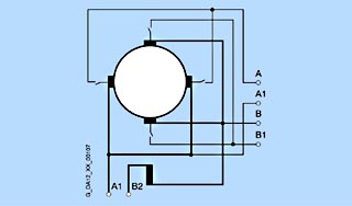
AC tachometers generate a three-phase AC voltage proportional to their speed, which is rectified into a DC voltage for tachometers with an integrated or externally mounted three-phase bridge circuit rectifier. The polarity of this DC voltage is not dependent on the direction of rotation. AC tachometers are preferably only used for drives with one direction of rotation; they offer the advantage that they are almost completely maintenance-free.
The rectifier has a linearity error of approx. 1.4 V due to the diode threshold, which however remains insignificant at the rated speeds involved.
DC-Tachometers
DC tachometers with permanent magnet generate a DC voltage proportional to their speed, the polarity of which changes with the drive direction of rotation. They are preferably used for multi-quadrant drives.
Pulse generators
Pulse generators are pulse frequency proportional to their speed. They are preferably used for digital speed displays and for highly accurate speed closed-loop controls.
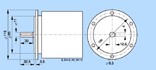
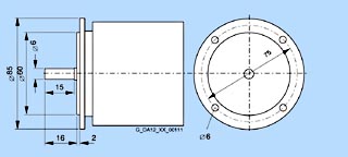
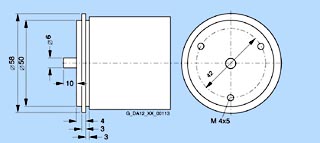
For mounting on the motors various tachometers and pulse generators are designated (refer to Catalog DA 12 · 2004, chapter 3 "Selection and Ordering – Options").
The most important data are specified in the tables below. Further information can be taken from the web sides of the individual manufacturers.
Technical data of the tachometers (according to actually valid manufacturers' information):
Manufacturer |
Type |
Max. permissible operating speed |
No-load voltage
V
0
|
Calibration tolerance |
Linearity tolerance |
No-load temperature response |
Degree of protection |
|---|---|---|---|---|---|---|---|
RPM |
mV/RPM |
% |
% |
%/K | |||
Hubner, Berlin |
TDP 0.09LT-3 |
10000 |
40 |
±3 |
?0.15 |
±0.005 |
IP56 IEC 34-5 |
TDP 0,2LT-4 |
10000 |
60 |
±1 |
?0.15 |
±0.005 |
IP55 IEC 34-5 | |
GTB 9.06L/420K |
9000 |
20 |
±5 |
?0.15 |
±0.005 |
IP68 IEC 34-5 | |
GMP 1,0LT-4 |
6000 |
100 |
±3 |
?0.5 |
±0.005 |
IP55 IEC 34-5 | |
Radio-Energie |
REO 444 R |
10000 |
60 |
±1 |
?0.15 |
±0.005 |
IP54 IEC 34-5 |
Thalheim |
TD 3 A4 KA |
12000 |
30 |
±3 |
?1 |
±0.02 |
IP66 IEC 529 |
Technical data of the pulse generators (according to actually valid manufacturers' information):
Manufacturer |
Type |
Pulses per revolution |
Logic level |
Max. permissible operating speed RPM |
Supply voltage V 0 |
No-load current drain |
Switching frequency
f
max
|
Degree of protection |
|---|---|---|---|---|---|---|---|---|
RPM |
V |
mA |
kHz |
|||||
Hubner, Berlin |
POG 9 D 500 |
2 x 500 |
HTL |
12000 |
+9 ... +30 |
100 |
120 |
IP56 IEC 34-5 |
POG 9 D 600 |
2 x 600 |
HTL |
12000 |
+9 ... +30 |
100 |
120 |
IP56 IEC 34-5 | |
POG 9 D 1024 |
2 x 1024 |
HTL |
12000 |
+9 ... +30 |
100 |
120 |
IP56 IEC 34-5 | |
POG 10 D 1024 |
2 x 1024 |
HTL |
10000 |
+9 ... +30 |
100 |
120 |
IP66 IEC 34-5 | |
Heidenhain |
ROD 436.001E |
2 x 1024 |
HTL |
12000 |
+10 ... +30 |
150 |
300 |
IP67 EN 60529 |
Besides the speed sensors specified in the list of options, further types and versions of speed sensors can be obtained and mounted order-specifically by the factory. The technical data and the possible designs and combinations of tachometers or pulse generators can be found in the catalog`s supply programs of the following manufacturers:
Hubner Berlinwww.huebner-berlin.de
Hubner Gie?enwww.huebner-giessen.de
Heidenhaindrehgeber.heidenhain.de
Radio Energiewww.radio-energie.fr
Thalheimwww.thalheim.de
The desired generator type has to be described precisely and has to be asked for in the factory together with the motor. On ordering, optionY70 = "tachometer/pulse generator in special design“ has to be specified and additionally in the plain text the order and type number as well as the manufacturer. The desired generators can be obtained and mounted by the factory. Please observe for generator types with long delivery time that the delivery time for motors can be extended.
Speed sensor mounting prepared
The motors can be delivered without generator, but with a mounting flange and mounting parts for installation of a speed sensor.
Mounting parts are available for the following generators:
Short code G75
Hubner Berlin: OG 9; POG 9; POG10; TDP 0,2 LT
Hubner Gie?en: FG4
Radio Energie: REO 444R
Leine & Linde: L&L 850
Short code G76
Hubner Berlin: TDP 0,09
Short code G77
Hubner Berlin: TDP 1,2; GMP 1,0L (type of construction B5n)

Short code G78
Heidenhain: ROD 436
Couplings
REVOLEX pin couplings are recommended for power transmission.
Source of supply, e.g.:
KTR Kupplungstechnik GmbH
Postfach 1763
48407 Rheine
Tel. +49 (0)5971-798-0
Fax. +49 (0)5971-798-440
www.ktr.de
Brakes
Motors of up to inclusive frame size 280 are available with mounting brake (1GF and 1HA on request)
- Up to frame size 160 with single-disk spring-operated brake or multiple-disk spring-operated brake, manufactured by Binder company (degree of protection IP43)
- with dihedral spring pressure brake, manufactured by Stromag, from frame size 180 upwards (degree of protection IP55, micro switch built in).
The brakes are of the electromagnetic type for dry operation which use the force of an electromagnetic field to offset the braking force exerted by the springs.
The spring-operated brakes are applied when de-energized and released when energized. The brake locks the drive in the braked position (holding brake which is activated when no current flows). Please inquire if the emergency stop function is required.
The brakes are designed for a 230 V AC 40 to 60 Hz supply. The silicon rectifier is accommodated in the brake terminal box. 24 V DC supply is possible for frame sizes up to 160 (refer to Catalog DA 12 · 2004, chapter 3 "Selection and Ordering – Options“).
The tables below show the assignment of the brake sizes to the motors as well as the output absorbed by the brake and the brake weight.
The assignment is chosen in a way that the torque of the brake lies within the order of magnitude of the motor torque.
Motors with brake mounting are only available in vibration severity grade N.
Furthermore the following designs are available:
A combinated mounting of brake and tachometer (short code G92) is only possible for a tachometer/pulse generator with own bearing, i.e. the pulse generator ROD436 from Heidenhain company cannot be mounted in connection with a brake.
The brakes for motors of frame sizes 180 to 280 have a manual release device, which can for example cancel the braking effect manually in the case of a power failure. For motors of up to frame size 160 a manual release device is offered as an option (short code K82, refer to Catalog DA 12 · 2004, chapter 3 "Selection and Ordering - Options“).
For mounting on |
Brake (single-disk spring-operated brake, type 77 600) Standard assignment, short code G40 | |||
|---|---|---|---|---|
1GG5 . . .
|
Size |
Braking torque |
Power consumption |
Approx. net weight |
Nm |
VA |
kg | ||
. . . . 102
|
13 |
32 |
69 |
4.5 |
. . . . 112
|
16 |
60 |
96 |
9 |
. . . . 132
|
19 |
130 |
122 |
13.5 |
. . . . 162
|
24 |
240 |
190 |
26.5 |
For mounting on |
Brakes (short code G40) | |||
Size |
Braking torque |
Power consumption |
Approx. net weight | |
Nm |
VA |
kg | ||
1GG6 . . .
|
Multiple-disk spring-operated brake, type 72 627 C 13 (Binder) | |||
. . . . 162
|
25 |
480 |
190 |
35 |
1GG6 . . .
|
Dihedral spring pressure brake NFA (Stromag) | |||
. . . . 186 |
40/61-6 |
610 |
207 |
50 |
. . . . 188 |
63/76-6 |
760 |
243 |
60 |
. . . . 206
|
63/96-6 |
960 |
243 |
60 |
. . . . 226
|
100/150-6 |
1500 |
285 |
90 |
. . . . 256
|
160/220-6 |
2200 |
372 |
160 |
. . . . 286
|
250/330-6 |
3300 |
452 |
210 |
Installation and mounting of motors
Sliding rail with fixing bolts and straining screw in accordance with DIN 42923
Sliding rails are used for slight and easy tensioning of a machine belt, if there is no belt tensioning roller. They are fixed to the foundation with rag bolts or foundation blocks.
The assignment of the sliding rails to the motor size has to be taken from DIN 42923. For Motors from frame size 355 there are no standardized sliding rails.
The separate fan mounting on 1GG5 motors cannot take place at the same side of the straining screw.
Source of supply:
Lutgert & Co.
Postfach 4251
D-33276 Guthersloh
Tel. +49 (0)5241-7407-0
Fax. +49 (0)5241-7407-90
www.luetgert-antriebe.de
e-mail: info@luetgert-antriebe.de
Foundation blocks in accordance with DIN 799
Foundation blocks are embedded into the stone foundation and grouted in with concrete. They are used for fixing middle sized machines, sliding rails, pedestal bearings, base frames and similar things. After unscrewing the fixing bolts, it is possible to move the machine at any place without having to lift it. On first installation, the foundation blocks, which are screwed down with the machine (without shims) and are provided with taper pins, are not grouted in until the machine is completely adjusted. On this occasion, the machine is set down lower by 2 to 3 mm. Only at the final assembly the difference in the frame sizes is balanced by placing plates underneath. On repeated removal and new installation the taper pins assure the exact position of the machine without renewed alignment.
Source of supply:
Lutgert & Co.
Postfach 4251
D-33276 Guthersloh
Tel. +49 (0)5241-7407-0
Fax. +49 (0)5241-7407-90
www.luetgert-antriebe.de
e-mail: info@luetgert-antriebe.de
Taper pins in accordance with DIN 258 with threaded stems and constant taper length
Taper pins are used with parts which are repeatedly unlatched. The drilling is rubbed out conically with a taper reamer until the pin can be pressed in manually so that the flat taper point lies approx. 3 to 4 mm above the edge of the hole. By driving the pin in with a hammer, the right position is reached. By unscrewing and driving in the nut, the pin can be taken out of the drilling again. Standardized taper pins are available at your specialist dealer.
Source of supply, e.g.:
Otto Roth GmbH & Co. KG
Baumleinsberg 54
91233 Neukirchen am Sand
Tel. +49 (0)9123-94 00 10
Fax. +49 (0)9123-94 00 15
 Приводная техника