
Types of construction
The types of construction of the motors are in accordance with DIN EN 60034, part 7, flange design in accordance with DIN 42948.
The desired type of construction must be specified by code digit in position 12 of the order number. In case of code digit "9", the short code must also be specified in accordance with the table below.
Types of construction for motors frame size 100 to 2801)
Type of construction |
Position: |
1 |
2 |
3 |
4 |
5 |
6 |
7 |
- |
8 |
9 |
10 |
11 |
12 |
- |
13 |
14 |
15 |
16 |
- |
Z |
Short code | ||
|---|---|---|---|---|---|---|---|---|---|---|---|---|---|---|---|---|---|---|---|---|---|---|---|---|
IM B3 |
 |
0 |
||||||||||||||||||||||
IM B35 |
 |
6 |
||||||||||||||||||||||
IM B5 2) |
 |
1 |
||||||||||||||||||||||
IM V1 2) |
 |
 |
4 |
|||||||||||||||||||||
IM B6 3) |
 |
9 |
M1A | |||||||||||||||||||||
IM B7 3) |
 |
9 |
M1B | |||||||||||||||||||||
IM B8 |
 |
9 |
M1C | |||||||||||||||||||||
IM V15 |
 |
9 |
M1H | |||||||||||||||||||||
IM V3 2) |
 |
9 |
M1G | |||||||||||||||||||||
IM V35 |
 |
9 |
M1J | |||||||||||||||||||||
IM V5 3) |
 |
 |
9 |
M1D | ||||||||||||||||||||
IM V6 3) |
 |
9 |
M1E | |||||||||||||||||||||
1) DC motors of frame size 355 to 630 are offered in the catalog only in the IM B3 type of construction.
2) For type of construction IM B5 the motors are supplied in IM B35, for IM V1 in IM V15 and for IM V3 in IM V35.
1HQ and 1HS motors are only available in type of construction IM B3 and IM B35.
3) For these types of construction, special support feet must be provided for relieving the strain on the fixing bolts in the transverse direction (from frame size 180 upwards).
Cooling type, degree of protection
The cooling types of the motors are in accordance with DIN EN 60034-6 or IEC 60034-6, the degrees of protection in accordance with DIN EN 60034-5 or IEC 60034?5.
For an overview of the cooling types and degrees of protection for standard DC motors refer to section "Overview of cooling types and degrees of protection", page 6.
The degree of protection symbols for motors and terminal boxes specified in the catalog consist of 2 code letters and 2 code digits. These are described below:
IP: International Protection: Code letters designating the degree of protection against contact with live or moving parts inside the enclosure and the ingress of solid bodies and water.
1st digit: Degree of protection against contact with Iive and moving parts and the ingress of solid bodies.
2nd digit: Degree of protection against the ingress of water.
Note:
The higher the 1st and 2nd digit, the higher the degree of protection.
For vertical types of construction the degree of protection IP23 is only granted, if the air inlet point shows downwards.
The short codes for the cooling types of the motors specified in the catalog consist of 2 letters (IC = International Cooling) and a combination of digits and letters. Further details can be found in DIN EN 60034-6.
Cooling, air flow direction
The cooling air is normally fed from commutator end (non-drive end NDE) to the output end (drive end DE), where it discharges through shutter openings or gill-type plates to the left and right. The motor output is reduced by approximately 12 % for motors of frame size up to 160 if one side of the air outlet has to be blocked, the out put is only reduced by 6 % if the duct is on one side (no shutter ribs in this case).
Arrangement of the air inlet or outlet openings on DE and NDE:
Frame size |
Air intake and discharge opening on |
|---|---|
100 to 160 (1G.5) |
2x: on the side, right and left |
160 to 200 (1G.6) |
3x: on the right, left and top |
225 to 630 |
on all 4 sides |
The air flow direction can be changed from the drive end to the non-drive end for 1GG and 1GH motors, short code K64 (refer to Catalog DA 12 · 2004, chapter 3 "Selection and Ordering - Options". De-rating may be necessary in certain cases (refer to the table below).
In many application fields, but especially when machines are operated with weak loading, low cooling air inlet temperature or under difficult ambient conditions, it is recommended to ventilate the machine from DE to NDE.
Refer to Catalog DA 12 · 2004, chapter 3 "Selection and Ordering - Options" for possible duct connections for 1GH motors.
Motor output for air flow direction from the drive end to the non-drive end (the armature circuit code letter is position 10 of the order number):
Motor type 1GF5 . . . |
Armature circuit |
||||||||||
|---|---|---|---|---|---|---|---|---|---|---|---|
A |
B |
C |
D |
E |
F |
G |
H |
J |
K |
L | |
% |
% |
% |
% |
% |
% |
% |
% |
% |
% |
% | |
. . . . 102 . . . . 104 . . . . 106 . . . . 108 |
100 100 100 100 |
100 100 100 100 |
100 100 100 90 |
100 100 100 90 |
100 100 90 90 |
100 100 90 100 |
100 90 100 90 |
100 90 100 90 |
100 100 90 100 |
100 100 90 - |
100 90 90 - |
. . . . 114 . . . . 116 . . . . 118 |
100 - - |
100 100 100 |
100 100 100 |
100 100 100 |
100 100 100 |
100 100 100 |
100 100 100 |
100 90 100 |
100 90 90 |
90 90 90 |
90 - 90 |
. . . . 132 . . . . 134 . . . . 136 |
100 100 - |
100 90 100 |
100 100 100 |
90 100 100 |
100 100 90 |
100 100 90 |
100 90 90 |
100 90 90 |
100 90 90 |
90 90 90 |
- 90 - |
. . . . 162 . . . . 164 . . . . 166 |
100 100 100 |
100 100 100 |
100 100 100 |
100 100 100 |
100 100 100 |
100 90 100 |
100 90 100 |
90 90 100 |
90 90 100 |
90 90 100 |
90 90 100 |
1GG6 . . . |
|||||||||||
. . . . 186 . . . . 188 |
100 100 |
100 100 |
100 100 |
95 95 |
100 100 |
90 90 |
80 80 |
80 80 |
– – |
– – |
– – |
. . . . 206 . . . . 208 |
100 100 |
100 100 |
95 95 |
100 100 |
90 90 |
80 80 |
80 80 |
80 80 |
– – |
– – |
– – |
. . . . 226 . . . . 228 |
100 100 |
100 100 |
100 100 |
100 100 |
90 90 |
85 90 |
85 80 |
80 75 |
– – |
– – |
– – |
. . . . 256 . . . . 258 |
100 100 |
100 100 |
100 100 |
100 100 |
100 100 |
90 90 |
85 85 |
80 80 |
– – |
– – |
– – |
. . . . 286 . . . . 288 |
100 100 |
100 100 |
100 100 |
100 100 |
95 95 |
85 85 |
90 90 |
90 85 |
– – |
– – |
– – |
Motor type 1GG7 . . . |
Armature circuit |
||||||||||
|---|---|---|---|---|---|---|---|---|---|---|---|
A |
B |
C |
D |
E |
F |
G |
H |
J |
K |
L | |
% |
% |
% |
% |
% |
% |
% |
% |
% |
% |
% | |
. . . . 351 . . . . 352 . . . . 353 . . . . 354 . . . . 355 |
100 100 100 100 100 |
100 100 100 100 100 |
100 100 100 100 100 |
100 100 100 100 95 |
100 100 100 100 90 |
100 100 95 95 90 |
95 90 90 90 85 |
90 85 85 80 80 |
90 85 80 80 80 |
– – – – – |
– – – – – |
. . . . 401 . . . . 402 . . . . 403 . . . . 404 . . . . 405 |
100 100 100 100 100 |
100 100 100 100 100 |
100 100 100 100 100 |
100 100 100 100 100 |
100 100 100 100 100 |
100 100 100 100 95 |
100 100 100 95 95 |
95 95 90 90 90 |
90 90 85 85 80 |
– – – – – |
– – – – – |
. . . . 451 . . . . 452 . . . . 453 . . . . 454 . . . . 455 |
100 100 100 100 100 |
100 100 100 100 100 |
100 100 100 100 100 |
100 100 100 100 100 |
100 100 100 100 100 |
100 100 100 100 100 |
100 100 100 95 95 |
100 100 95 90 90 |
100 100 95 90 90 |
– – – – – |
– – – – – |
1GG5 . . . |
|||||||||||
. . . . 500 to . . . . 630 |
on request |
||||||||||
Cooling air flow, pressure head
For the ventilation of 1GH motors the ducts must be dimensioned in such a way that the values for the cooling air flowV and the pressure head ?p in the table below are maintained.
If ducts are mounted on 1GF or 1GG motors, these must be dimensioned in such a way that the permissible pressure head ?p is not exceeded.
For motors 1GF5 . . . |
Cooling air flowV |
Permissible pressure drop ?p in the ducts for motors 1GF, 1GG |
Required pressure head ?p for motors 1GH |
|---|---|---|---|
m3/s |
Pa |
Pa | |
. . . . 102 . . . . 104 to 108 |
0.045 0.06 |
40 45 |
300 500 |
. . . . 114 and 116 . . . . 118 |
0.07 0.08 |
45 70 |
500 650 |
. . . . 132 to 136 |
0.09 |
45 |
500 |
. . . . 162 to 166 |
0.2 |
60 |
700 |
1GF6 . . . |
|||
. . . . 160 |
0.20 |
60 |
1300 |
. . . . 180 |
0.30 |
70 |
1350 |
. . . . 200 |
0.35 |
70 |
1250 |
. . . . 225 |
0.50 |
80 |
1600 |
. . . . 250 |
0.60 |
80 |
1500 |
. . . . 280 |
0.75 |
80 |
1600 |
1GG7 . . . |
|||
. . . . 351 . . . . 352 . . . . 353 . . . . 354 . . . . 355 |
1.3 |
100 |
1800 1900 2000 2300 2500 |
. . . . 401 . . . . 402 . . . . 403 . . . . 404 . . . . 405 |
1.6 |
100 |
1800 1900 2100 2200 2500 |
. . . . 451 . . . . 452 . . . . 453 . . . . 454 . . . . 455 |
2.0 |
100 |
1700 1800 2000 2200 2400 |
1GG5 . . . |
|||
. . . . 500 . . . . 630 |
2.0 3.0 |
70 70 |
1400 1350 |
Air-to-water and air-to-air coolers
Motors with air-to-water cooler (1HS) are ventilated by means of a fan unit with a three-phase motor mounted in the cooler assembly. The heated internal air is recooled via a water cooler. With a cooling water inlet temperature of 25 °C 1HS motors have the same output as 1GH motors.
The standard water connections (as viewed from the drive end) are located on the right. For 1HS6 186 to 288 and 1HS7 351 to 455 a subsequent changeover of the cooler for water connections on the left is only possible for special design water coolers.
Motors 1HS5 500 to 635 are equipped with coolers with removable water boxes. In this case a later relocation of the cooler is also possible.
Normal cooling water temperature rise up to 10 K, water pressure up to 6 bar (test pressure 9 bar).
If you feel uncertain about the required cooling types, please inquire a cooler with water analysis.
Standard version:
Coolers with copper tubes and copper collectors (not removable) for non-aggressive water which has been cleaned to remove any solid particles. Vibration stress up to 0.6 g (63 Hz).
Special design (short code M10):
Coolers with CuNi10Fe tubes, CuZn38SnAl tube sheets and removable plastic-coated steel chambers for water with a pH value of between 5 and 9 and a maximum chloride content of 25 g/l.
The cooling tubes can be cleaned mechanically.
Motors of frame size 250 to 630 can be provided with a filter in the internal air circuit.
Air-to-water cooler data:
Water volumetric flow required |
Pressure drop in cooling element | ||
|---|---|---|---|
Motor type |
l/min |
m3/h |
bar |
1HS6 186 1HS6 206 1HS6 226 1HS6 256 1HS6 286 |
39 45 58 75 95 |
2.3 2.7 3.5 4.5 5.7 |
0.1 0.1 0.15 0.15 0.22 |
1HS7 35. 1HS7 40. 1HS7 45. |
95 110 125 |
5.7 6.6 7.5 |
0.13 0.2 0.26 |
1HS5 50. 1HS5 631 |
115 150 |
6.9 9.0 |
0.3 0.37 |
Motors with air-to-air cooler (1HQ) are ventilated by means of two fan units with a three-phase motor mounted in the cooler assembly. The recooling of the heated internal air takes place via an air-/air-heat exchanger. The fan unit for the internal air circuit is mounted axially, the fan unit for the external air circuit is mounted on top of the cooler. 1HQ motors have an output of approximately 70 % of 1GH motors.
Fan units
1GF, 1GG, 1HQ and 1HS motors have built-on fan units with three-phase motor, supply voltage 380 to 420 V AC, 50 Hz or 380 to 500 V.
For operation at 60 Hz with motors from frame size 250, a plain text indication in the order is necessary.
The specific data of fan motors can be taken from the following tables.
Assignment table of the fan motors:
Motor type |
Fan motor |
I
max
|
I
max
|
|---|---|---|---|
A |
A | ||
1GG5 102 to 108 |
2CW5355-0 |
0.3 |
0.28 |
1GG5 114 to 116 |
2CW5355-0 |
0.3 |
0.28 |
1GG5 118 |
2CW5366-1 |
0.9 |
0.63 |
1GG5 132 to 136 |
2CW5366-1 |
0.9 |
0.63 |
1GG5 162 to 166 |
2CW5367-1 |
0.88 |
0.97 |
1GF5 114 to 116 |
2CW5355-0 |
0.3 |
0.28 |
1GF5 132 to 136 |
2CW5366-1 |
0.9 |
0.63 |
1GF5 162 to 166 |
2CW5367-1 |
0.88 |
0.97 |
1GG6 162 to 166 |
2CW5307-7 |
2.5 |
2.2 |
The fan units are designed as follows:
- Wide range winding 380 V to 500 V Y
- Cooling medium temperature 40 °C
- Type of construction IM B14
- 2-pole
Motor circuit breakers have to be adjusted to the specified maximum currents.
Motor type |
Three-phase fan motor |
Rated voltage |
Connection |
Frequency |
Rated output |
Rated current |
|---|---|---|---|---|---|---|
Size |
V |
Hz |
kW |
A | ||
1GG6 182 to 184 |
80 |
400 |
Y |
50 |
1.1 |
2.5 |
460 |
Y |
60 |
1.2 |
2.4 | ||
1GG6 186 to 222 |
90 S |
400 |
Y |
50 |
1.5 |
3.5 |
460 |
Y |
60 |
1.7 |
3.4 | ||
1GG6 226 to 288 |
100 L |
400 |
Y |
50 |
3 |
6.3 |
460 |
Y |
60 |
3.4 |
6 | ||
1GG7 351 to 455 |
132 S |
400 |
? |
50 |
7.5 |
14.7 |
460 |
? |
60 |
8.6 |
14.2 | ||
1GG5 500 to 635 |
132 S (2 x) |
400 |
? |
50 |
7.5 |
14.5 |
460 |
? |
60 |
8.6 |
14 | ||
1HS6 186 to 208 |
90 S |
400 |
Y |
50 |
1.5 |
3.5 |
460 |
Y |
60 |
1.7 |
3.4 | ||
1HS6 222 to 288 |
100 L |
400 |
Y |
50 |
3 |
6.3 |
460 |
Y |
60 |
3.4 |
6 | ||
1HS7 351 to 455 |
132 S |
400 |
? |
50 |
7.5 |
14.7 |
460 |
? |
60 |
8.6 |
14.2 | ||
1HS5 500 to 635 |
132 S (2 x) |
400 |
? |
50 |
7.5 |
14.5 |
460 |
? |
60 |
8.6 |
14 | ||
Internal air | ||||||
1HQ6 186 to 208 |
90 S |
400 |
Y |
50 |
1.5 |
3.5 |
460 |
Y |
60 |
1.7 |
3.4 | ||
1HQ6 222 to 288 |
100 L |
400 |
Y |
50 |
3 |
6.3 |
460 |
Y |
60 |
3.4 |
6 | ||
1HQ7 351 to 455 |
132 S |
400 |
? |
50 |
7.5 |
14.7 |
460 |
? |
60 |
8.6 |
14.2 | ||
1HQ5 500 to 635 |
132 S (2 x) |
400 |
? |
50 |
7.5 |
14.7 |
460 |
? |
60 |
8.6 |
14.2 | ||
External air | ||||||
1HQ6 186 to 208 |
80 |
400 |
Y |
50 |
0.75 |
1.73 |
2-pole |
460 |
Y |
60 |
0.86 |
||
1HQ6 226 to 288 |
90 S |
400 |
Y |
50 |
1.5 |
3.25 |
2-pole |
460 |
Y |
60 |
1.75 |
3.1 | |
1HQ7 351 to 455 |
100 L |
400 |
Y |
50 |
2 |
4.7 |
4-pole |
460 |
Y |
60 |
2.55 |
||
1HQ5 500 to 504 |
100 L |
400 |
? |
50 |
3 |
6.4 |
4-pole |
460 |
? |
60 |
3.45 |
||
1HQ5 631 to 635 |
112 M |
400 |
? |
50 |
4 |
8.2 |
4-pole |
460 |
? |
60 |
4.6 |
||
The fan motors are designed as follows:
- Type of construction B5
- Degree of protection IP55
- Insulation class F
- Cooling medium temperature 55 °C
- Voltage tolerance ±10 %
- Rating plate with 50 and 60 Hz data
Three-phase terminals of fan motors
All fan motors are equipped with a plastic terminal box which is mounted on the fan motor. The terminal box is freely accessible.
Each terminal box has 6 terminals. Threaded holes with metric threads are provided for cable entries according to the table below.
For motors up to a frame size of 160 loose adapter pieces for metric threads according to PG threads are enclosed in the terminal boxes. Only plastic hubs can be used.
Assignment of the entry drillings of the fan motor terminal boxes:
For Motor type |
Cable gland |
Max. conductor cross-section mm2 |
|---|---|---|
1GG5 102 to 116 |
1x M16 x 1.5 and 1x M25 x 1.5 |
1.5 |
1GG5 118 to 166 |
1x M16 x 1.5 and 1x M25 x 1.5 |
2.5 |
1GF5 114 and 116 |
1x M16 x 1.5 and 1x M25 x 1.5 |
1.5 |
1GF5 132 ro 166 |
1x M16 x 1.5 and 1x M25 x 1.5 |
2.5 |
1GG6 162 to 166 |
1x M16 x 1.5 and 1x M25 x 1.5 |
2.5 |
1GG6 186 to 208 |
2x M25 x 1.5 |
2.5 |
1GG6 226 to 288 |
2x M25 x 1.5 |
4 |
1GG7 351 to 455 |
2x M32 x 1.5 |
6 |
1GG5 500 to 635 |
2x M32 x 1.5 |
6 |
Internal air circuit |
External air circuit (1HQ motors only) | |||
|---|---|---|---|---|
Cable gland |
Max. conductor cross-section |
Cable gland |
Max. conductor cross-section | |
For Motor type |
mm2 |
mm2 | ||
1HQ6 186 to 208 |
2x M25 x 1.5 |
2.5 |
2x M25 x 1.5 |
2.5 |
226 to 288 |
2x M25 x 1.5 |
4 |
2x M25 x 1.5 |
2.5 |
1HQ7 351 to 455 |
2x M32 x 1.5 |
6 |
2x M25 x 1.5 |
4 |
1HQ5 500 to 633 |
2x M32 x 1.5 |
6 |
2x M25 x 1.5 |
4 |
1HS6 186 to 208 |
2x M25 x 1.5 |
2.5 |
– |
– |
226 to 288 |
2x M25 x 1.5 |
4 |
– |
– |
1HS7 351 to 455 |
2x M32 x 1.5 |
6 |
– |
– |
1HS5 500 to 633 |
2x M32 x 1.5 |
6 |
– |
– |
Filter and silencer mounting
Air filter
If the installation place of the motors supplies only cooling air with unsufficient percentage of purity, the mounting of a filter is necessary.
If in the case of very high percentage of dust at the location of use the effect of the filter is not sufficient or if the maintenance intervals for the filters are too short, it is recommended to use a surface-cooled motor in degree of protection IP54 or a with a duct connection separately cooled motor of the 1GH type in degree of protection IP54/IC37.
A dry-type filter can be mounted on all 1GF and 1GG motors (refer to Catalog DA 12 · 2004, chapter 3 "Selection and ordering - Options"). The filter is mounted axially in front of the fan intake.
Filters can also be retrofitted. Derating is not required.
The filtration efficiency is 99 % for a dust particle size of 10 µm. The efficiency decreases for smaller particle sizes.
The noise levels are reduced by 1 to 2 dB for motor frame sizes from 160 to 280 if a filter is mounted.
Silencer
For 1GG motors from frame size 180 a silencer can be mounted on the air inlet of the separate fan. Thereby the sound pressure levelLpA of the 1GG motors can be reduced by approximately 5 dB.
The mounting of a silencer is also possible in combination with an air filter.
Noise levels
The sound-pressure levelsLpA and the sound power levelLWA (including tolerance) specified in the table below apply at full load up to 2000 RPM for B6C converter connection and standard separate fan unit at 50 Hz
The values forLpA andLWA are significantly lower than the values permitted in accordance with EN 60034-9.
Measuring-surface sound-pressure level |
A-sound power level |
|||
|---|---|---|---|---|
For Motors |
dB(A) |
dB(A) |
||
1GF5 . . . |
||||
. . . . 100 |
68 |
80 |
||
1H.5 . . . |
1HC5 |
1HA5 |
1HC5 |
1HA5 |
. . . . 100 |
55 |
– |
67 |
– |
1GF6 . . . |
||||
. . . . 160 |
73 |
86 |
||
1G.6 . . . |
1GH6 and 1HS6 |
1GG6 and 1HQ6 |
1GH6 and 1HS6 |
1GG6 and 1HQ6 |
. . . . 180 |
72 |
76 |
85 |
90 |
The sound power levelLWA is the sum of the measuring-surface level and measuring-surface sound-pressure levelLpA.
A motor noise no-load/load differential of 3 to 5 dB can be assumed when making comparisons with the standard. The no-load noise levels, when fed from pure DC, are approximately 3 dB below the noise values for converter supply.
When using a silencer the specified noise levels can be reduced by approx. 5 dB.
Bearings
Motors up to and including frame size 200 have pre-lubricated rolling contact bearings. Larger motors have regreasable rolling contact bearings.
The original grease charge of the pre-lubricated bearings normally lasts for two years, after which time it must be replaced.
Motors with regreasable bearings can be re-lubricated while the motor is running.
For extreme conditions, e.g. high cooling temperatures (exceeding 60°C), motors, frame sizes 112 to 200, normally fitted with pre-lubricated bearings, can be supplied with regreasable bearings (refer to Catalog DA 12 · 2004, chapter 3 "Selection and Ordering - Options").
A locating bearing is used at the drive end and a floating bearing at the non-drive end of motors up to frame size 132. For motors, frame size 180 and upwards, the non-drive end has a locating bearing and the drive end a floating bearing.
1G.5/1H.5 motors, frame size 160, are fitted with a locating bearing at the drive end, 1G.6 motors, frame size 160, at the non-drive end.
Depending on the degree of protection or the arrangement of the bearings, the bearings are sealed using grease-packed grooves and/or axial shaft sealing rings or INA ring disks or sealing disks (RS bearings) preventing the ingress of dust.
For motors, frame size up to 280, the bearings can accept the weight of the rotor including that of the coupling half if the motor is mounted in an inclined or vertical position.
Please inquire if the motor is to be subject to higher axial loading and for motors with frame size from 355 upwards.
Refer to the table below for the bearing assignments.
The bearing assignments are valid for motors with all types of construction and vibration severity grades N and R.
Bearing assignment |
Deep-groove ball bearings in accordance with DIN 625 |
|||
|---|---|---|---|---|
Motortyp |
Cylindrical roller bearing in accordance with DIN 5412 |
|||
Drive end bearing |
Non-drive end bearing |
|||
|
Standard version |
Double-bearing design 4) (short code K20) |
Standard version |
Ausfuhrung fur Nachschmiereinrichtung (Kurzangabe K40) |
. . . . 102 |
6206-C3 |
NU 2206 E+ |
6205-RSJ-C3 |
– |
. . . . 112 |
6208-C3 |
NU 208 E+ |
6206-RSJ-C3 |
6206-C3 |
. . . . 132 |
6309-C3 |
NU 309 E 5)+ |
6208-RSJ-C3 |
6208-C3 |
. . . . 162 |
6212-C3 |
NU 312 E 5)+ |
6309-RSJ-C3 |
6309-C3 |
4) Not available for 1GA5/1HA5 motors.
5) With special bearing according to factory information (with restricted air intake).
Motor type 1G.6 . . . |
Standard version |
Bearing for high cantilever force |
Special design bearing for extremely high cantilever forces | ||
|---|---|---|---|---|---|
Drive end bearing |
Non-drive end bearing |
Drive end bearing |
Non-drive end bearing | ||
. . . . 160 |
6213?RSJC3 |
6213?RSJC3 |
NU 213E 6) |
- |
- |
1G.7 . . . |
|||||
. . . . 355 |
6226 C3 |
6226 C3 |
– |
– |
– |
1G.5 . . . |
|||||
. . . . 500 |
NU 230 |
NU 226 + 6226 C3 |
– |
– |
– |
6) With restricted radial air intake according to factory information.
Permissible cantilever forces
When using power transmission elements, which result in cantilever forces of the shaft end (belt drive or direct mounting on gears), it has to be taken care that the limits specified in the cantilever force diagrams aren`t exceeded. Possibly it is necessary to use a cylindrical roller bearing at the drive end (short code K20, refer to Catalog DA 12 · 2004, chapter 3 "Selection and Ordering - Options").
The permissible cantilever forces for motors, frame size up to 450 are specified in the following cantilever force diagrams. For motors with frame size 355 to 450 it is assumed that no cantilever forces appear, as the output takes place via a coupling. In this case cantilever force diagrams only exist for bearing increased cantilever forces.
The cantilever force diagrams are only applicable for standard drive shaft ends. The permissible cantilever forces for non-drive shaft ends and non-standard drive shaft ends the permissible cantilever forces must be determined for each particular case (please inquire).
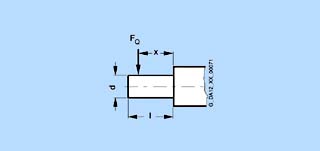
The dimension x specified in the cantilever force diagrams is the distance between the line of action of the force FQ and the shaft shoulder. The dimension xmax corresponds to the length l of the shaft end.
The permissible cantilever forces for radial loading at the drive shaft end are specified in the following cantilever force diagrams (based on a normal bearing service life of 20 000 hours)
Cantilever force diagrams - Standard bearing design

Motors 1G.5/1H.5 102 to 1G.5/1H.5 108

Motors 1G.5 112

Motors 1G.5/1H.5 114 to 1G.5/1H.5 118

Motors 1G.5/1H.5 132 to 1G.5/1H.5 136

Motors 1G.5/1H.5 162 to 1G.5/1H.5 166
Cantilever force diagrams - Double-bearing design

Motors 1G.5 102 to 1G.5 108

Motors 1G.5 114 and 116

Motors 1G.5 118

Motors 1G.5 132 to 1G.5 136

Motors 1G.5 162 to 1G.5 166
Cantilever force diagrams - Standard bearing design

Motors 1G.6 16.

Motors 1G.6/1H.6 186/188

Motors 1G.6/1H.6 206/208

Motors 1G.6/1H.6 226/228

Motors 1G.6/1H.6 256/258

Motors 1G.6/1H.6 286/288
Cantilever force diagrams - Heavy-duty bearings for high cantilever forces
The roller bearings used here may be damaged under no-load conditions. Observe the minimum cantilever forces.

Minimum cantilever force 1.2 kN Motors 1G.6 16.

Minimum cantilever force 4 kN Motors 1G.6/1H.6 186/188

Minimum cantilever force 4.5 kN Motors 1G.6/1H.6 206/208

Minimum cantilever force 6 kN Motors 1G.6/1H.6 226/228

Minimum cantilever force 7.5 kN Motors 1G.6/1H.6 256/258

Minimum cantilever force 9 kN Motors 1G.6/1H.6 286/288

Minimum cantilever force 11 kN Motors 1G.7/1H.7 351/352

Minimum cantilever force 11 kN Motors 1G.7/1H.7 353/354/355

Minimum cantilever force 14.5 kN Motors 1G.7/1H.7 401/402/403

Minimum cantilever force 16.5 kN Motors 1G.7/1H.7 404/405

Minimum cantilever force 14.5 kN Motors 1G.7/1H.7 451/452/453/454/455
Cantilever force diagrams - Special design bearings for extremely high cantilever forces

Minimum cantilever force 6 kN Motors 1G.6/1H.6 186 and 188

Minimum cantilever force 7 kN Motors 1G.6/1H.6 206 and 208

Minimum cantilever force 9 kN Motors 1G.6/1H.6 226 and 228

Minimum cantilever force 10.5 kN Motors 1G.6/1H.6 256 and 258

Minimum cantilever force 12.5 kN Motors 1G.6/1H.6 286 and 288
Motors 1G.6/1H.6 with special design bearings for extremely high cantilever forces are longer.
Frame size |
Dimension k |
|---|---|
180/200 |
+30 |
225/250/280 |
+40 |
Shaft ends
Shaft ends conform to DIN 748, part 3 and the centring holes (60°) to DIN 332, part 2.
The keyways are machined in accordance with DIN 6885, sheet 1. Shaft keys are always supplied with the motors.
All shaft ends have an undercut, whereby the design for motors from frame sizes 180 upwards is in accordance with form E in accordance with DIN 509.
If required, motors can also be supplied with a non-standard shaft end in accordance with the table below (refer to Catalog DA 12 · 2004, chapter 3 "Selection and Ordering - Options"). The permissible stressing depends on the desired dimensions.
A second shaft end can be provided for motors (except for 1GF motors) provided that no accessories are axially mounted. The non-drive shaft end is only suitable for flexible coupling outputs.
With the exception of 1GF motors, the shaft is accessible or can be made accessible at the non-drive end for speed measurement purposes.
Shaft end diameter |
Length |
|||
|---|---|---|---|---|
Frame size |
Larger than standard |
Smaller than standard |
Longer than standard |
Shorter than standard |
100 to 160 |
no |
yes |
no |
yes |
180 and upwards |
no |
yes |
yes 7) |
yes |
7) Up to approx. double the length.
Mechanical performance, vibrations
All motors are equipped with low-noise and low-vibration rolling-contact bearings. All of the motors in Catalog DA 12 · 2004 fulfill vibration severity grade N.
Refer to the table below for recommended maximum vibration severity grades for electric motors in accordance with DIN EN 60034-14 (up to 3600 RPM) and factory specifications.
There are no design restrictions for vibration severity grade R.
For flange-mounted motors, frame sizes 100 to 160 with vibration severity grades S, the reduced tolerances for the mounting flange (permissible positional variances for the shaft end) are maintained in accordance with DIN 42955. If these reduced tolerances are also to be maintained for flange-mounted motors, vibration severity grade R, these motors must be ordered with high-precision flanges grade R in accordance with DIN 42955.
From frame size 180 the vibration severity grade S is only practicable with deep groove ball bearing at the drive end and with horizontal foot-mounted types. From frame size 355 vibration severity grade S on request.
For frame sizes |
|||||
|---|---|---|---|---|---|
100 to 132 |
160 |
180 to 225 |
250 to 400 | ||
Speed range |
Max. vibration velocity valuesVrms | ||||
Vibration severity grade |
RPM |
mm/s |
mm/s |
mm/s |
mm/s |
N (standard) |
600 to 3600 |
1.8 |
2.8 |
2.8 |
4.5 |
R (reduced) |
600 to 1800 |
0.71 |
1.12 |
1.12 |
1.8 |
S (non-standard) |
600 to 1800 |
0.45 |
0.71 |
0.71 |
1.12 |
SR (please inquire) (with vibration severity grade values S divided by 1.6) |
600 to 1800 |
0.28 |
0.45 |
– |
– |
8) Not for 1G.5 108/1HC5 108.
Permissible vibration levels from external sources
The system vibration characteristics as a result of the mechanical drive output elements, alignment and mounting, as well as the influence of external vibrations can result in higher motor vibration values. The motor vibration values specified in the table below should not be exceeded with a view to perfect commutation, low brush wear and long bearing service life.
In certain cases, it may be necessary to completely balance the motor with the mechanical output drive elements.
Vibration frequency |
Vibration values | ||
|---|---|---|---|
Hz |
Frame size |
| |
<6.3 |
Vibration displacement s (mm) |
?0.16 |
?0.25 |
6.3 to 63 |
Vibration velocity |
?4.5 |
?7.1 |
>63 |
Vibration acceleration |
?2.55 |
?4.0 |
Balancing
The rotors of 1G.5/1H.5 and 1G.6/1H.6 motors are dynamically balanced with complete fitted key (full-key balancing).
The rotors of 1G.7/1H.7 motors are balanced with half key (half-key balancing).
This should be taken into account when balancing the drive elements.
Foundation
The systems engineer has to assure a resonance-free mounting of the motor.
For the design of the foundation DIN 4024, part 2 has to be observed.
Terminal boxes
All motors have a terminal box for connecting the main DC supply. As standard for all motors the terminal box is mounted on the right side when viewing on the drive side shaft end. If required, it can also be located on top (except for motors with top-mounted coolers) or on the left-hand side. For horizontal types of construction and terminal boxes on the right, the cable entry is at the bottom. The terminal box can be subsequently rotated through 90°. All terminal boxes have degree of protection IP55.
DC terminals
The terminal box (refer to table below) has 2 field winding terminals and 2 armature terminals as well as additional terminals for PTC thermistor sensors, space heaters or similar.
Labelled terminals are available for connecting the protective conductor. For motors, frame size from 180 upwards (and 1G.6 16.), an additional external protective conductor on the outer side of the motor is available (for cross-sections refer to table "Conductor sizes and cable entries“).
Main supply conductors
The dimensions of the main supply conductors have to be in accordance with DIN VDE 0298. The amount of the necessary parallel supplies is determined by
- the maximal connectable conductor cross section
- the cable type
- the cable laying
- the ambient temperature and
- the permissible current in accordance with DIN VDE 0298.
Cable entries
Depending on the motor size various terminal box versions are used. Terminal boxes with cable entry drillings are closed by sealing plugs.
Terminal boxes of larger motors have a cable entry plate which is normally supplied undrilled. It can be unscrewed from the terminal box for drilling (for details refer to table "Conductor sizes and cable entries“).
Assignment of the terminal boxes:
For motor |
Terminal box (max. permissible terminal current) | ||||||||||
|---|---|---|---|---|---|---|---|---|---|---|---|
|
gk 230 |
gk 330 |
gk 420 |
gk 427 |
gk 527 |
gk 602 |
1XB7 540 |
1XB7 700 |
1XB7 710 |
1XB7 942 |
1XB7 720 |
102 to 108 |
• |
– |
– |
– |
– |
– |
– |
– |
– |
– |
– |
112 to 116 |
– |
• |
– |
– |
– |
– |
– |
– |
– |
– |
– |
132 to 136 |
– |
• |
• |
• |
• |
– |
– |
– |
– |
– |
– |
160 (1G.5) |
– |
– |
• |
• |
• |
– |
– |
– |
– |
– |
– |
160 (1G.6) |
– |
– |
– |
– |
– |
• |
– |
– |
– |
– |
– |
182 to 184 |
– |
– |
– |
– |
– |
– |
• |
– |
– |
– |
– |
186 to 188 |
– |
– |
– |
– |
– |
– |
– |
• |
– |
– |
– |
202 to 204 |
– |
– |
– |
– |
– |
– |
• |
– |
– |
– |
– |
206 to 208 |
– |
– |
– |
– |
– |
– |
– |
• |
– |
– |
– |
222 to 224 |
– |
– |
– |
– |
– |
– |
– |
• |
– |
– |
– |
226 to 288 |
– |
– |
– |
– |
– |
– |
– |
– |
• |
– |
– |
351 to 455 |
– |
– |
– |
– |
– |
– |
– |
– |
– |
– |
• |
501 to 635 |
– |
– |
– |
– |
– |
– |
– |
– |
• |
• |
– |
Conductor sizes and cable entries:
Terminal box Type |
Max. permissible rated current |
Connecting thread for field current |
Connecting thread for armature current |
Max. conductor cross-section per terminal |
Max. protective conductor cross-section |
Max No. of cable entries |
Max. external protective conductor cross-section |
Cable entry plate |
|---|---|---|---|---|---|---|---|---|
A |
mm2 |
mm2 |
mm2 |
|||||
gk 230 |
36 |
M4 |
M4 |
6 |
6 |
2 x Pg 21 |
Sealing plugs | |
gk 330 |
59 |
M5 |
M5 |
16 |
16 |
2 x Pg 29 |
Sealing plugs | |
gk 420 |
77 |
M5 |
M5 |
25 |
25 |
2 x Pg 29 |
Sealing plugs | |
gk 427 |
105 |
M4 |
M10 |
35 |
35 |
2 x Pg 29 and 2 x Pg 21 |
Sealing plugs | |
gk 527 |
239 |
M4 |
M10 |
150 |
150 |
2 x Pg 29 and 2 x Pg 16 |
undrilled | |
gk 602 |
268 |
M4 |
M10 |
185 |
185 |
3 x Pg 29 + 2 x Pg 16 |
185 |
undrilled |
1XB7 540 |
360 |
M5 |
M16 |
185 |
2 x 70 |
2 x M36 x 2 + 2 x M18 x 1.5 |
2 x 240 |
undrilled |
1XB7 700 |
600 |
M6 |
M16 |
2 x 240 |
2 x 240 |
8 x M36 x 2 + 4 x M24 x 1.5 |
2 x 240 |
undrilled |
1XB7 710 |
1200 |
M6 |
M16 |
4 x 240 |
2 x 240 |
10 x M45 x 2 + 4 x M24 x 1.5 |
2 x 240 |
undrilled |
1XB7 720 |
2000 |
M6 |
M16 |
6 x 240 |
6 x 240 |
18 x M40 x 1.5 + 5 x M20 x 1.5 |
6 x 240 |
undrilled |
1XB7 942 |
2500 |
M6 |
M16 |
9 x 240 |
4 x 300 |
20 x M50 x 1.5 + 4 x M32 x 1.5 |
2 x 240 |
undrilled |
Terminal designations of DC motors
The terminal designation of DC motors is in accordance with DIN EN 60034-8.
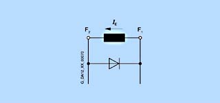
For fixing the rotational direction in relation to the armature current and the field direction, applies the rule that on operation of a DC motor in clockwise rotation the polarity of currents L+ and L- corresponds to the polarity of connections A1 and A2, as well as to connections F1 and F2.
For counter-clockwise direction the polarity of the supplies has to be changed either to the armature or the excitation field.
Motor winding or winding type or conductors in the DC supply system |
Terminal designations to | |
|---|---|---|
DC motors |
Armature winding |
A1 – A2 |
Symmetrically-split |
B1 – B2 | |
Field winding (series) |
D1 – D2 | |
Field winding (shunt) |
E1 – E2 | |
Field winding (separate field) |
F1 – F2 | |
Field winding (separate field) |
F1 – F2 | |
DC supply system |
Positive conductor |
L+ |
Designation of auxiliary terminal boxes
The designation of the auxiliary terminal boxes is made by using the designation of the supplementary device in connection with:
- a pre-set digit, characterizing the respective circle or unit,
- a post-set digit, characterizing the function of the conductor.

Example of a thermistor sensor with a positive temperature coefficient
BA |
AC Brake |
|---|---|
BD |
DC Brake |
BW |
Brushwear detector |
HE |
Heater |
R |
Resistance thermometer |
TP |
Thermistor with positive temperature coefficient |
int finish
The standard colour is grey in accordance with RAL 7016.
The paint finish can be carried out as standard or non-standard paint finish. Refer to the table below for the structure.
All colours deviating from the standard must be ordered using the short code Y53 for standard paint finish or Y54 for non-standard paint finish. The desired colour must be specified in plain text (RAL ….).
Additional measures regarding insulation and surface protection are necessary (additional charge) if the motors are subject to chemically aggressive gases as encountered, for example, in bleaching plants in the textile industry.
Version |
Suitable for climate classification in accordance with |
Resistance to heat |
Structure of primer for cast iron, steel and sheet steel components |
Final coat |
|---|---|---|---|---|
Standard paint finish |
Moderate (extended) for inside and outside |
As for final coat |
Up to frame size 160: From frame size 180: | |
Briefly: up to 100 % relative humidity for temperatures up to +30 °C Continuously: up to 85 % relative humidity for temperatures up to +25 °C |
Briefly: +120 °C Continuously: +100 °C |
|||
Special paint finish |
Worldwide (global) for use outdoors |
As for final coat |
Up to frame size 160: From frame size 180: | |
Briefly: up to 100 % relative humidity for temperatures up to +35 °C Continuously: up to 98 % relative humidity for temperatures up to +30 °C Additionally: for aggressive ambient conditions with up to 1 % acid and alkaline concentrations or continuous moisture in sheltered areas |
Briefly: +140 °C Continuously: +120 °C |
 Приводная техника