|
| | | | |
Function | Description |
|---|
Functions of the closed-loop control in the armature circuit | Speed setpoint | The source of the speed setpoint and additional setpoints can be freely selected by making the appropriate parameter settings: - Entered using analog values 0 to ± 10 V, 0 to ± 20 mA, 4 to 20 mA
- Entered via the PROFIBUS fieldbus interface, Ethernet interface for PROFINET (optional)
- Using the integrated motorized potentiometer
- Using binectors with the functions: Fixed setpoint, jogging, crawl
- Entered via serial interfaces of the SINAMICS DC MASTER
- Entered via supplementary modules
The scaling is realized so that 100 % setpoint (formed from the main setpoint and supplementary setpoints) corresponds to the maximum motor speed. The setpoint can be limited to a minimum and maximum value via a parameter or connector. Further, additional points are provided in the firmware e.g. in order to be able to enter supplementary setpoints before or after the ramp-function generator. The "setpoint enable function" can be selected using a binector. After a parameterizable filter function (PT1 element), the summed setpoint is transferred to the setpoint input of the speed controller. In this case, the ramp-function generator is also active. | Actual speed | One of four sources can be selected as signal for the speed actual value. - Analog tachometer
The voltage of the tachogenerator at maximum speed can be between 8 and 270 V. Adaptation to the voltage is realized using parameters. - Pulse encoder
The pulse encoder type, the number of pulses per revolution and the maximum speed are set using parameters. Encoder signals (symmetrical: with additional, inverted track, unsymmetrical: referred to ground) up to a maximum differential voltage of 27 V can be processed by the evaluation electronics.
The rated voltage range (5 or 15 V) for the encoder is selected via parameters. The power supply for the pulse encoder can be taken from the DC Converter for a rated voltage of 15 V.
5 V encoders require an external power supply. The pulse encoder is evaluated across the three tracks:
Track 1, track 2 and zero mark. However, pulse encoders without zero mark can also be used. A position actual value can be sensed using the zero mark. The maximum frequency of the encoder pulses can be 300 kHz. It is recommended that pulse encoders with at least 1024 pulses per revolution are used (due to the smooth running operation at low speeds). - Operation without tachometer with EMF control
A speed actual value encoder is not required for closed-loop EMF control. In this case, the output voltage of the device is measured in the DC converter. The measured armature voltage is compensated by the internal voltage drop across the motor (IR compensation). The level of compensation is automatically determined during the current controller optimization run. The accuracy of this control method, which is defined by the temperature-dependent change in the motor armature circuit resistance, is approximately 5 %. We recommend that the current controller optimization run is repeated when the motor is in the warm operating condition to achieve a higher degree of precision. The closed-loop EMF control can be used if the requirements on the precision are not so high, if it is not possible to mount an encoder and the motor is operated in the armature voltage control range.
Notice: In this mode, EMF-dependent field weakening is not possible. - Freely selectable speed actual value signal
For this mode, any connector number can be selected as speed actual value signal.
This setting is especially selected if the speed actual value sensing is implemented on a supplementary technology module.
Before the speed actual value is transferred to the speed controller, it can be smoothed using a parameterizable smoothing element (PT1 element) and two adjustable bandstop filters. Bandstop filters are used primarily for the purpose of filtering out resonant frequencies caused by mechanical resonance. The resonant frequency and the filter quality factor can be set.
| Ramp-function generator | When there is a step change in the setpoint applied at its input, the ramp-function generator converts the setpoint into a signal with a steady rate of rise. Ramp-up time and ramp-down time can be selected independently of one another. In addition, the ramp-function generator has initial and final rounding-off (jerk limiting) that are effective at the beginning and end of the ramp-up time. All of the times for the ramp-function generator can be set independently of one another. Three parameter sets are available for the ramp-function generator times; these can be selected via binary select inputs or a serial interface (via binectors). The ramp-up function generator parameters can be switched over in operation. In addition, a multiplication factor can be applied to the value of parameter set 1 via a connector (to change the ramp-function generator data via a connector). When entering ramp-function generator times with the value zero, the speed setpoint is directly input into the speed controller. | Speed controller | The speed controller compares the setpoint and actual value of the speed and if there is a deviation, enters an appropriate current setpoint into the current controller (principle: Speed control with lower-level current controller). The speed controller is implemented as PI controller with additional D component that can be selected. Further, a switchable droop function can be parameterized. All of the controller parameters can be adjusted independently of one another. The value for Kp (gain) can be adapted depending on a connector signal (external or internal). In this case, the P gain of the speed controller can be adapted depending on the speed actual value, current actual value, setpoint-actual value distance or the wound roll diameter. This can be pre-controlled in order to achieve a high dynamic performance in the speed control loop. For this purpose, e.g. depending on the friction and the moment of inertia of the drive, a torque setpoint signal can be added after the speed controller. The friction and moment of inertia compensation are determined using an automatic optimization run. The output quantity of the speed controller can be directly adjusted via parameter after the controller has been enabled. Depending on the parameterization, the speed controller can be bypassed and the converter controlled either with closed-loop torque or current control. In addition, it is also possible to switch between speed control/torque control in operation using the "leading/following switchover" selection function. The function can be selected as binector using a binary user-assignable terminal or a serial interface. The torque setpoint is input via a selectable connector and can therefore come from an analog user-assignable terminal or via a serial interface. A limiting controller is active when in the following drive state (torque or current controlled operation). In this case, depending on a speed limit that can be selected using parameters, the limiting controller can intervene in order to prevent the drive accelerating in an uncontrolled fashion. In this case, the drive is limited to an adjustable speed deviation. | Torque limiting | The speed controller output represents the torque setpoint or current setpoint depending on what has been parameterized .In torque-controlled operation, the speed controller output is weighted with the machine flux О¦ and transferred to a current limiting stage as a current setpoint. Torque control is applied primarily in field weakening operation in order to limit the maximum motor torque independent of the speed. The following functions are available: - Independent setting of positive and negative torque limits using parameters.
- Switchover of the torque limit using a binector as a function of a parameterizable switchover speed.
- Free input of a torque limit by means of a connector signal, e.g. via an analog input or via serial interface.
The lowest specified quantity should always be effective as the actual torque limit. Additional torque setpoints can be added after the torque limit. | Current limiting | The current limit that can be adjusted after the torque limit is used to protect the converter and the motor. The lowest specified quantity is always effective as the actual current limit. The following current limit values can be set: - Independent setting of positive and negative current limits using parameters (maximum motor current setting).
- Free input of a current limit using a connector, e.g. from an analog input or via a serial interface.
- Separate setting of current limit using parameters for stopping and quick stop.
- Speed-dependent current limiting: An automatically initiated, speed-dependent reduction of the current limit at highspeeds can be parameterized (commutation limit curve of the motor).
I2t monitoring of the power section: The thermal state of the thyristors is calculated for all current values. When the thyristor limit temperature is reached, the unit responds as a function of parameter settings, i.e. the converter current is reduced to the rated DC current or the unit is shut down with a fault message. This function is used to protect the thyristors. | Current controller | The current controller is implemented as PI controller with P gain and integral time that can be set independently from one another. The P and I components can also be deactivated (pure P controller or pure I controller). The current actual value is sensed using a current transformer on the three-phase side and is fed to the current controller via a load resistor and rectification after analog-digital conversion. The resolution is 10 bits for the converter rated current. The current limit output is used as current setpoint. The current controller output transfers the firing angle to the gating unit – the pre-control function is effective in parallel. | Pre-control | The pre-control in the current control loop improves the dynamic performance of the closed-loop control. This allows rise times of between 6 and 9 ms in the current control loop. The pre-control is effective dependent on the current setpoint and EMF of the motor and ensures – for intermittent and continuous current or when the torque direction is reversed – that the required firing angle is quickly transferred as setpoint to the gating unit. | Auto-reversing module | In conjunction with the current control loop, the auto-reversing module (only for units with four-quadrant drives) ensures the logical sequence of all of the operations and processes required to change the torque direction. The torque direction can also be disabled when required via parameter. | Gating unit | The gating unit generates the firing pulses for the power section thyristors in synchronism with the line supply voltage. The synchronization is independent of the speed and the electronics supply and is sensed at the power section. The timing of the firing pulses is defined by the output values of the current controller and the pre-control. The firing angle limit can be set using parameters. In a frequency range from 45 to 65 Hz, the gating unit automatically adapts itself to the actual line frequency. | Functions of the closed-loop control in the field circuit | EMF controller | The EMF controller compares the setpoint and actual value of the EMF (induced motor voltage) and enters the setpoint for the field current controller. This therefore permits field weakening control that is dependent on the EMF.
The EMF controller operates as PI controller; P and I components can be adjusted independently of one another and/or the controller can be operated as pure P controller or pure I controller. A pre-control function operates in parallel to the EMF controller. Depending on the speed, it pre-controls the field current setpoint using an automatically recorded field characteristic (refer to the optimization runs). There is an adding point after the EMF controller, where the supplementary field current setpoints can be entered either via a connector, via an analog input or a serial interface. The limit is then effective for the field current setpoint. In this case, the field current setpoint can be limited to a minimum and a maximum value that can be set independently from one another. The limit is realized using a parameter or a connector. The minimum for the upper limit or the maximum for the lower limit is effective. | Field current controller | The field current controller is a PI controller – where Kp and Tn can be independently set. It can also be operated as pure P and I controller. A pre-control function operates in parallel to the field current controller. This calculates and sets the firing angle for the field circuit as a function of current setpoint and line supply voltage. The pre-control supports the current controller and ensures that the field circuit has the appropriate dynamic performance. | Gating unit | The gating unit generates the firing pulses for the power section thyristors in synchronism with the line supply voltage in the field circuit. The synchronization is detected in the power section and is therefore independent of the electronics power supply. The timing of the firing pulses is defined by the output values of the current controller and the pre-control. The firing angle limit can be set using parameters. In a frequency range from 45 to 65 Hz, the gating unit automatically adapts itself to the actual line supply voltage. | Communication between drive components | DRIVE-CLiQ | Communication between SINAMICS components is realized using the standard internal SINAMICS interface DRIVE-CLiQ (this is an abbreviation for Drive Component Link with IQ). This couples the Control Unit with the connected drive components (e.g. DC Converter, Terminal Modules etc.). DRIVE-CLiQ provides standard digital interfaces for all SINAMICS drives. This permits modularization of the drive functions and thus increased flexibility for customized solutions (allows power and intelligence to be separated). The DRIVE-CLiQ hardware is based on the Industrial Ethernet standard and uses twisted-pair cables. The DRIVE-CLiQ line provides the transmit and receive signals and also the 24 V power supply. Setpoints and actual values, control commands, status feedback signals and electronic rating plate data of the drive components are transferred via DRIVE-CLiQ. Only original Siemens cables must be used for DRIVE-CLiQ cables. As a result of the special transfer and damping properties, only these cables can guarantee that the system functions perfectly. | SINAMICS Link | SINAMICS Link allows data to be directly exchanged between several (2 to 64) Control Units. A higher-level master is not required. The following Control Units support SINAMICS Link: For use of SINAMICS Link, all of the Control Units must be equipped with the CBE20 Communication Board (option G20). In addition, a memory card (options S01, S02) is required for the Advanced CUD. Communication can either be synchronous (only CU320-2) or non-synchronous or a combination of both. Each participant can send and receive up to 16 process data words. For instance, SINAMICS Link can be used for the following applications: - Torque distribution for n drives
- Setpoint cascading for n drives
- Load distribution of drives coupled through a material web
- Master/slave function
- Couplings between SINAMICS units
| OALINK | OALINK (Open Application Link) allows two Control Units to exchange data directly. A higher-level master is not required. The following Control Units support the OALINK: The communication system is based on DRIVE-CLiQ which means that no hardware components other than the DRIVE-CLiQ line are required. OALINK must be loaded as a technology package. A software license is required when it is installed on the CU320-2. The article number for the Certificate of License (CoL) is 6SL3077-0AA01-0AB0. No license is required on the Control Unit CUD of the SINAMICS DC MASTER. OALINK permits the cyclic transmission of a total of 120 words which can comprise the following data types: - Integer16 (1 word)
- Integer32 (2 words)
- FloatingPoint32 (2 words)
For instance, OALINK can be used for the following applications: - Torque distribution for n drives
- Setpoint cascading for n drives
- Load distribution of drives coupled through a material web
- Technology expansion for the SINAMICS DCM (CU320-2 as T400 substitute)
- Couplings between SINAMICS units
|
Overview, closed-loop control structure  Single-phase connection For DC Converters up to 125 A and up to 575 V AC, the full functionality of the devices is available even when supplied through only two conductors. 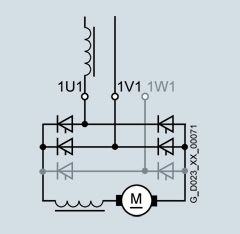 This means, that in a retrofit project for example, a converter with a single-phase connection can be integrated into state-of-the-art communication concepts (TIA) without requiring any changes to the existing machine or plant. The unit is connected to the line supply via terminals 1U1 and 1V1. It is mandatory that a single-phase commutating reactor or a transformer with 4 % uk is provided, which only supplies the DC Converter involved.
Commutating reactor and transformer should be selected according to the rated motor current of the armature circuit. In this B2 circuit, the line current is equal to the DC current in the armature circuit. All of the other line-side drive components should be dimensioned according to this. Further, due to the higher current ripple when compared to six-pulse operation, a smoothing reactor must be provided in the DC circuit. Please contact the motor manufacturer when dimensioning the smoothing reactor. The associated technical specifications of the three-phase converter connected to a single phase can be found in section "Technical specifications" under DC Converter. (Compared to three-phase operation, the rated DC current is derated by a factor of 0.7.) Rated output voltage for single-phase connection Line supply | Rated output voltage for single-phase connection |
|---|
| Two-quadrant operation | Four-quadrant operation | V | V | V | 230 | 180 | 160 | 400 | 320 | 280 | 480 | 385 | 335 | 575 | 460 | 400 |
Coolant temperature and installation altitude Current derating The permissible coolant temperatures and installation altitudes for SINAMICS DC MASTER as well as the associated maximum permissible load of the DC Converters in continuous operation can be taken from the following table (the load is specified as a % of the rated DC current). | Maximum permissible load of the DC Converter in continuous operation (the load is specified as a % of the rated DC current) |
|---|
| Installation altitude above sea level (The derating factors for values in between can be determined using linear interpolation.) | Ambient or coolant temperature | 1000 m | 2000 m | 3000 m | 4000 m | 5000 m | | | Units up to 125 A | Units from 210 A and higher | Units up to 125 A | Units from 210 A and higher | Units up to 125 A | Units from 210 A and higher | Units up to 125 A | Units from 210 A and higher | Units up to 125 A | Units from 210 A and higher | 30 °C | 100 % | 100 % | 100 % | 98 % | 96 % | 88 % | 86 % | 78 % | 78 % | 70 % | 35 °C | 100 % | 100 % | 100 % | 93 % | 90 % | 83 % | 80 % | 73 % | | | 40 °C | 100 % | 100 % | 94 % | 88 % | 84 % | 78 % | | | | | 45 °C | 100 % | 95 % | 88 % | 83 % | | | | | | | 50 °C | 94 % | 90 % | 82 % | 78 % | | | | | | | 55 °C | 88 % | | | | | | | | | |
Voltage derating The units can be operated up to an installation altitude of 4000 m above sea level with the specified rated supply voltages. The line supply voltages may have overvoltage category III with respect to ground. For installation altitudes above 4000 m, in some cases, it will be necessary to reduce the supply voltage or ensure that overvoltage category II is maintained. Detailed information is provided in the operating instructions.
|
|
