|
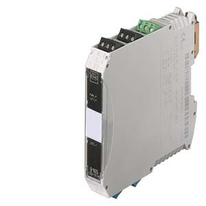
SITRANS I200 output isolator with HART
|
|
Input
|
|
|
Input signal
|
0/4 ... 20 mA with HART
|
|
Functional range
|
0 ... 24 mA
|
|
Max. input current
|
50 mA
|
|
Input resistance (changeable switch LI)
|
225 ?/550 ?
|
|
Communication signal
|
Bidirectional HART transmission, 0.5 kHz ... 30 kHz
|
|
Ex i output
|
|
|
Output signal
|
0/4 ... 20 mA with HART
|
|
Connectable load resistance
|
0 ... 800 ?
|
|
Min. load resistance for short-circuit monitoring
|
150 ?
|
|
Residual ripple
|
? 50 mV
|
|
No-load voltage
|
? 25.6 V
|
|
Response time (10% ... 90%)
|
? 100 ?s
|
|
Transmission characteristics
Input/output
|
1:1
(0 ... 20 mA --> 0 ... 20 mA, 4 ... 20 mA --> 4 ... 20 mA)
|
|
Measuring accuracy
Accuracy, typical data expressed as % of calibrated span at UN, 23 °C
|
|
|
Linearity error
|
? 0.1%
|
|
Offset error
|
? 0.1%
|
|
Temperature influence
|
? 0.1%/10 K
|
|
Power supply effect within voltage range
|
? 0.01%
|
|
Load resistance effect
|
? 0.02%
|
|
Rated conditions
|
|
|
Degree of protection of enclosure
|
IP30
|
|
Degree of protection of terminals
|
IP20
|
|
Ambient conditions
|
|
|
|
-20 °C ... +70 °C (-4 ... +158 °F)
(see "Operating instructions")
|
|
|
-40 °C ... +80 °C (-40 ... +176 °F)
|
- Relative humidity (no condensation)
|
? 95%
|
|
Electromagnetic compatibility
|
Tested under the following standards and regulations: EN 61326-1 Use in the industrial environment
|
|
Design
|
|
|
Screw terminals
|
|
|
|
|
|
|
0.2 ... 2.5 mm2 (0.00031 ... 0.0039 in2)
|
|
|
0.2 ... 2.5 mm2 (0.00031 ... 0.0039 in2)
|
- Flexible with end ferrules (without/with plastic ferrule)
|
0.25 ... 2.5 mm2 (0.00039 ... 0.0039 in2)
|
|
|
|
|
|
0.2 ... 1 mm2 (0.00031 ... 0.00155 in2)
|
|
|
0.2 ... 1.5 mm2 (0.00031 ... 0.0023 in2)
|
- Flexible with end ferrules
|
0.25 ... 1 mm2 (0.00039 ... 0.00155 in2)
|
|
Weight
|
Approx. 160 g (0.35 lb)
|
|
Type of installation
|
On DIN rail according to EN 50022 (NS35/15; NS35/7.5)
|
|
Mounting position
|
Vertical or horizontal
|
|
Enclosure material
|
PA 6.6
|
|
Fire protecting class (UL-94)
|
V0
|
|
Auxiliary power
|
|
|
Rated voltage UN
|
24 V DC
|
|
Voltage range
|
18 ... 31.2 V
|
|
Residual ripple within voltage range
|
? 3.6 VSS
|
|
Rated current (UN, 20 mA)
|
80 mA
|
|
Power consumption (UN, 20 mA)
|
1.3 W
|
|
Power loss (at UN, RL = 500 ?)
|
1.1 W
|
|
Operation indicator
|
Green "PWR" LED
|
|
Reverse polarity protection
|
Yes
|
|
Undervoltage monitoring
|
Yes (no faulty module/output states)
|
|
Electrical isolation
|
|
- Test voltage according to EN 60079-11
|
|
|
|
1.5 kV AC
|
- Ex i output to auxiliary power
|
1.5 kV AC
|
- Error contact to Ex i output
|
1.5 kV AC
|
- Test voltage according to EN 50178
|
|
|
|
350 V AC
|
- Error contact to auxiliary power and input
|
350 V AC
|
|
Error detection Ex i output
|
|
|
|
> 10 k?
|
|
|
< 15 ?
|
|
|
> 100 k?
|
- Open-circuit detection only for input current
|
? 3.6 mA
|
|
|
Activated/deactivated
|
|
|
LED red "LF"
|
- Error messaging and power supply failure
|
- Contact (30 V/100 mA), closed to ground in case of error
- pac-Bus, floating contact (30 V/100 mA)
|
|
Certificates and approvals
|
|
|
Explosion protection ATEX
|
|
- EC type-examination certificate
|
DMT 03 ATEX E 012 X
|
|
|
II 3 (1) G Ex nA nC [ia] IIC T4
II (1) D [Ex iaD]
|
|
Installation
|
In Zone 2, Div. 2 and in the safe area
|
|
Other approvals
|
USA (FM)
Canada (CSA)
Shipping (DNV)
|
|
Safety specifications (CENELEC)
|
|
|
|
25.6 V
|
|
|
96 mA
|
|
|
605 mW
|
- Max. connectable capacitance Co for IIC/IIB
|
103 nF/800 nF
|
- Max. connectable inductance Lo for IIC/IIB
|
1.9 mH/11 mH
|
- Internal capacitance Ci and inductance Li
|
Negligible
|
|
|
253 V
|
- Additional information and value combinations
|
See Certifications
|