
Online ISO dialect interpreter
In general, part programs for SINUMERIK controls are programmed according to DIN 66025 and relevant expansions. Part programs created according to the ISO standard (e.g., G codes from other manufacturers) can be read in, edited and executed on SINUMERIK controls using the online ISO dialect interpreter.
Operating modes
In the "Machine" operating area, you have a choice of three modes:
- JOG
JOG mode (jogging) is intended for the manual movement of axes and spindles, as well as for setting up the machine. The set-up functions are reference point approach, repositioning, traveling with the handwheel or in the predefined incremental mode, and redefinition of control zero (preset/set actual value). - MDA
In MDA (Manual Data Automatic/Manual Input) mode, you can enter individual program blocks or sequences of blocks, then execute them immediately via NC Start. The tested blocks can then be saved in part programs. The Teach In submode allows you to transfer sequences of motion to the MDA program by returning and storing positions. - AUTO
In AUTO mode, the part programs are executed fully automatically once they have been selected from the workpiece, part program or subprogram directory (normal operation). During AUTO mode it is possible to generate and correct another part program.
In the operating modes MDI and AUTO, you can modify the sequence of a program using the following program control functions:
SKP Skip block (up to eight skip levels)
DRY Dry run feedrate
ROV Rapid traverse override
SBL1 Single block with stop after sets of machine functions
SBL2 Single block with stop after every block
SBL3 Stop in cycle
M01 Programmed stop
DRF Differential resolver function
PRT Program test
Operating software languages (option N00)
The operating software supports the following languages as standard for user interface display texts: English, French, German, Italian, Simplified Chinese, and Spanish. The operator can switch back and forth online between foreground and background languages. Further languages can also be ordered with option N00.
Operator control without SINUMERIK OP (P00)
Operation of SINUMERIK via the VNC viewer requires a confirmation on the SINUMERIK operator panel that operation is now permitted via the VNC viewer. When a SINUMERIK operator panel is not used, this option can be used to suppress scanning of the confirmation.
Oscillation functions (option M34)
Oscillation functions
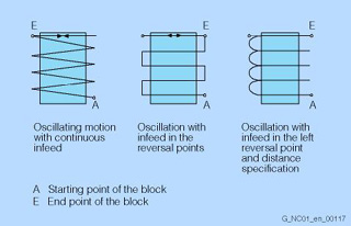
With this function, an axis oscillates at the programmed feedrate between two reversal points. A possible application is a grinding machine.
Asynchronous oscillation across block boundaries
Several reciprocating axes may be active. During reciprocating movement, other axes can interpolate at will. The reciprocating axis can be the input axis for the dynamic transformation or the master axis for gantry or coupled-motion axes.
Block-related oscillation
- Oscillation with infeed in both or only in the left or right reversal point. Infeed is possible along a programmable path prior to the reversal point.
- Sparking-out strokes after oscillation are possible.
Behavior of the reciprocating axis in the reversal point:
- A change of direction is initiated
- Without reaching the exact stop limit (soft reversal)
- After reaching the programmed position or
- After reaching the programmed position and expiration of the dwell time.
- The following manipulations are possible:
- Reciprocating movement and infeed can be terminated by deleting the residual distance
- Modification of the reversal points via CNC program, PLC, handwheel or direction keys
- Manipulation of the reciprocating axis feedrate via CNC program, PLC or override
- Control of the reciprocating movement via the PLC
The spindles can also perform reciprocating movement.
Pair of synchronized axes (gantry axes) (option M02)
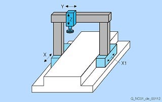
Gantry axes (pair of synchronized axes X/X1)
The "gantry axes" function can be used to traverse the axes of up to three pairs of mechanically-coupled axes simultaneously without mechanical offset. The actual values are continuously compared and even the smallest deviations corrected.
During both operation and programming, the axes defined in a gantry grouping are treated like machine axes. A gantry grouping consists of a master axis and up to 2 synchronized axes. 2 master axes can be coupled using curve table interpolation.
Path length evaluation (option M53)
> Synchronous actions
With path length evaluation, data in the control can be battery-backed, so that conclusions can be drawn in respect of the maintenance state of the machine.
In the first stage, the following data are acquired:
- Total travel path for each axis
- Total travel time for each axis
- Number of traversing actions per axis (stop - traverse - stop)
- Total sum of jerks per axis
These data are stored in the SRAM and are not affected by power on/off. Using an external utility, consistent data can, therefore, be achieved for the complete life cycle of a machine. These data can also be read through system variables in the part program and in synchronous actions.
Path switch signals/cam controller (option M07)
> High-speed CNC inputs/outputs
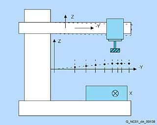
Position-dependent interface signals for the PLC can be set using position switching signals. The position values at which the signal output and a derivative action/hold up time are to be set can be programmed in the part program and entered via the setting data. The function can be controlled via the PLC.
The function is used for applications such as activating protection zones or position-dependent triggering of movements (e.g., hydraulic reciprocating axes during grinding).
Although position switching signals are output in the IPO cycle, they can also be output as switching outputs in the position-control cycle using the high-speed CNC inputs/outputs function.
Path-velocity-dependent analog output (option M37)
Using the path-velocity-dependent analog output, the current path velocity can be output in the interpolation cycle via a SIMATIC DP ET 200 analog module. The function is programmed via synchronous actions.
One application is laser power control.
Plain text display of user variables
> High-level CNC language
In addition to the predefined variables, programmers can define their own variables and assign values to them.
The variables are displayed in plain text format, e.g. definition: DEF INT NUMBER/Display: NUMBER or definition: DEF REAL DEPTH/Display: DEPTH.
PLC
SIMATIC STEP 7
The PLC on the SINUMERIK is programmed using the user-friendly SIMATIC STEP 7 software.
The STEP 7 programming software is based on the Windows operating system, and combines the proven STEP 5 programming functions with innovative further developments. The STL (statement list), FBD (function block diagram), and LAD (ladder diagram) programming languages are available.
The user can switch from one to the other using STEP 7 pull-down menus.
The following blocks are available for structured programming:
- Organization blocks (OBs)
- Function blocks (FBs) and function calls (FCs)
- Data blocks (DBs)
In addition, system function blocks (SFBs) and system functions (SFCs) integrated in the operating system can also be called.
The STEP 7 software package (for SIMATIC S7-300) is a standard component of SIMATIC programming devices (e.g., Field PG). A software package for standard industrial PCs is also available.
The PLC can also be programmed in other SIMATIC S7 high-level languages, such as S7 HiGraph and S7 Graph.
PLC/NCK interface
A number of functions can be executed via the NCK and PLC interface, ensuring excellent machining flexibility. Some of these are:
- Controlling positioning axes
- Executing synchronous actions (auxiliary functions)
- Reading and writing of NCK system variables by the PLC
- Reading and writing of NCK user variables by the PLC
ThePLC basic program, which is part of the toolbox, organizes the exchange of signals and data between the PLC user program and the NCK, PCU and machine control panel areas. In the case of signals and data, a distinction is made between the following groups:
- Cyclic signal transfer:
Commands from the PLC to the NCK (such as start, stop) and NCK status information (e.g., program running). The basic program carries out cyclic signal transfer at the beginning of the PLC cycle (OB 1). This ensures, for example, that the signals from the NCK remain constant throughout a PLC cycle. - Event-driven signal transfer NCK > PLC
PLC functions executed depending on the workpiece program are initiated via auxiliary functions in the workpiece program. If a block with auxiliary functions is executed, the type of auxiliary function determines whether the NCK has to wait for this function to execute (e.g., tool change) or whether the function will be executed together with the workpiece machining process (e.g., tool loading on milling machines with chain magazine). In order for CNC machining to be affected as little as possible, data transfer must be as fast as possible, yet reliable. It is therefore alarm and acknowledgment-controlled. The basic program evaluates the signals and data, sends an acknowledgment to the NCK, and transfers some of the data to OB40 and the rest to the user interface at the beginning of the cycle. If the data do not require an acknowledgment from the user, CNC machining is not affected. - Event-driven signal exchange PLC > NCK
Whenever the PLC sends a request to the NCK (such as a request to traverse an auxiliary axis), a PLC > NCK event-driven signal exchange takes place. Here again, the data transfer is acknowledgment-controlled. Such a signal transfer is initiated by the user program via an FB or FC. The associated FBs (function blocks) and FCs (function calls) are provided together with the basic program. - Messages
The acquisition and editing of user messages is handled by the basic program. The message signals are transferred to the basic program via a specified bit array. Here, the signals are evaluated, then transferred to the PLC diagnostic buffer when one of the message events occurs. If an OP is available, the messages are transferred to the OP and displayed on it.
PLC programming with HiGraph
The HiGraph method is used for describing technical systems and converting these descriptions into PLC programs.
With HiGraph, a machine or plant is seen as a combination of separate functional units. These functional units can be made up of basic mechanical and electrical elements. The HiGraph method is used in the automation of machines and plants where mechanical movements and time sequences take priority, e.g., on machine tools, transfer lines, conveyor, and transportation systems.
The HiGraph method can be used:
- During the machine and plant planning phase
- During the function planning phase
- During the design phase, e.g., of the mechanics
- For developing programs
- During the test stage and startup
- To operate the automated machine
- For maintenance and diagnostic tasks
Advantages of the HiGraph method:
- Quicker from design to result
- Shorter testing phases
- Structuring using symbolic names
- Application-oriented
- Object-oriented thinking
- Graphic programming
- Easy to use
- Reliable software
- Faster and simpler diagnostics
- Service at the machine level
PLC status
In its "diagnostics" operating area, the operator panel allows you to check and modify PLC status signals.
This allows you to do the following on site without a programming device:
- Check the input and output signals from the PLC's I/Os
- Carry out limited troubleshooting
- Check the NCK/PLC and PCU/PLC interface signals for diagnostic purposes
The status of the following data items can be displayed separately on the operator panel:
- Interface signals from/to the machine control panel
- NCK/PLC and PCU/PLC interface signals
- Data blocks, bit memories, timers, counters, inputs and outputs
The status of the above signals can be changed for tests. Signal combinations are also possible, and up to 10 addresses can be modified simultaneously.
PLC user memory
In the PLC user memory of the PLC CPU, the PLC user program and the user data are stored together with the PLC basic program.
The memory of the PLC CPU is divided up into load memory, work memory and system memory. Load memory is retentive, and takes the form of either integrated RAM or a RAM module (plug-in memory card). It contains data and program and decompiling information.
The load memory and the high-speed work memory for execution-relevant program tests provide sufficient space for user programs.
Polar coordinates
Programming in polar coordinates, it is possible to define positions with reference to a defined center point by specifying the radius and angle. The center point can be defined by an absolute dimension or incremental dimension.
Polynomial interpolation (option M18)
Polynomial interpolation
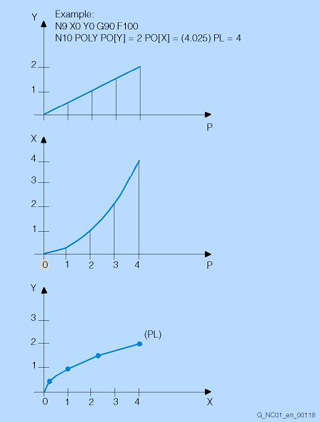
Curves can be interpolated using polynomial interpolation, whereby the CNC axes follow the function:
f(p) = a0 + a1p + a2p2 + a3p3 + a4p4 + a5p5 (polynomial, max. 5th degree)
The coefficient a0 is the end point of the previous block, a1 is calculated as the end point of the current block, a2, a3, a4, and a5 must be calculated externally and then programmed.
With polynomial interpolation, it is possible to generate many different curve characteristics, such as straight line, parabolic and exponential functions.
Polynomial interpolation primarily serves as an interface for programming externally generated spline curves. 5th degree polynomials can be used optimally if the coefficients are obtained directly from a CAD/CAM system (closer to the surface). A prerequisite for efficient utilization of this polynomial interpolation is, therefore, a corresponding CAD/CAM system.
Tool radius compensation can be used as in linear and circular interpolation.
Position monitoring
SINUMERIK controls provide extensive monitoring mechanisms for axis monitoring:
- Motion monitoring:
Contour monitoring, position monitoring, standstill monitoring, clamping monitoring, speed setpoint monitoring, actual speed monitoring, encoder monitoring - Static limits monitoring:
Limit switch monitoring, working area limitation
Position monitoring is always activated after termination of motion blocks according to the setpoint. To ensure that an axis is in position within a specified period of time, the timer configured in the machine data is started when a traversing block terminates; when the timer expires, a check is made to ascertain whether the following error fell below the limit value (machine data). When the specified fine exact stop limit has been reached or following output of a new position setpoint other than zero (e.g. after positioning to coarse exact stop and subsequent block change), position monitoring is deactivated and replaced by standstill monitoring.
Position monitoring is effective for linear and rotary axes as well as for position-controlled spindles. In follow-up mode, position monitoring is not active.
Positioning axes/auxiliary spindles (option B01-B26)
Positioning axes can execute movements simultaneously with machining, thus reducing non-productive times considerably. They can be used to advantage when controlling workpiece and tool feeders or tool magazines. They can be programmed with an axis-specific feedrate in the part program. Axis movement beyond block boundaries is also possible. Positioning axes can also be controlled by the PLC. This means that axis movements can be started independently of the part program without using up an additional machining channel.
Auxiliary spindles are speed-controlled spindle drives without an actual-position sensor, e.g., for tool drives.
Overview of possible functions:
- POS/SPOS/M3, M4, M5 (of CNC block)
- POSA/SPOSA (of CNC block, modal)
- FC18/POS/SPOS/M3, M4, M5 (PLC axes)
- PLC-VDI interface (M3, M4, M5 direct)
- OSCILL (asynchronous oscillating)
- OSCILL (synchronous oscillating)
- do POS/SPOS/M3, M4, M5
- Couplings (TRAIL, gantry and master-slave (positioning axis as slave axis), LEAD, EG, CT)
An additional positioning axis/auxiliary spindle cannot interpolate with other axes.
The following functions are not possible:
- Path axes/geometry axes/additional path axes/GEOAX()
- Spindles for thread cutting, tapping and thread cutting with compensating chuck
Positioning axes/spindles via synchronous actions
You can position axes/spindles depending on conditions (the actual values of other axes, high-speed inputs, etc.) with a special feedrate or speed to a specific setpoint via synchronous actions. Synchronous actions are executed in the interpolation cycle, are carried out in parallel with the actual workpiece machining procedure, and are not limited to CNC block boundaries.
These so-called command axes and command spindles can be started in the IPO cycle direct from the main program. The path to be traversed is either predefined or is calculated from real-time variables (with expanded arithmetic functions) in the IPO cycle. Spindles can be started, stopped or positioned asynchronously depending on input signals without PLC intervention.
Preset
With the Preset function, you can redefine the machine zero point in the machine coordinate system. The preset values affect machine axes. Axes do not move when Preset is active. but a new position value is entered for the current axis positions. Once the actual values have been reset, a new reference point approach is required before protection zones and software limit switches can be reactivated.
PROFIBUS tool and process monitoring (option M62)
Spotting errors before they happen. This is the motto for our SINUMERIK controls, which allow you to implement tool and process monitoring. Active power monitoring keeps an eye on such things as breakage, wear and missing tools. Precise operating status recognition and process optimization are also possible.
Using the PROFIBUS tool and process monitoring function, the digital drive data for torque, active power and actual current are directly transferred to a special PROFIBUS slave module. This hardware and the software for evaluation is offered, for example, by SINUMERIK Solution Partners. Up to 2 PROFIBUS slaves can be connected.
PROFINET
PROFINET is the open Industrial Ethernet standard of PROFIBUS International for automation systems. PROFINET is based on Industrial Ethernet and uses TCP/IP and IT standards.
Two versions are available:
- PROFINET CBA (Component Based Automation) for networking distributed plants, (component engineering)
- PROFINET IO (Input Output) for controlling sensors and actuators using one or several central controllers in production engineering.
PROFINET is supported by PROFIBUS International and the INTERBUS Club and has been included in standards IEC 61158 and IEC 61784 since 2003.
PROFINET includes:
- A multi-level real-time concept
- Simple field devices which operate IOs directly on Ethernet
- Design of modular, highly re-usable systems
- Simple integration of existing PROFIBUS or Interbus systems
PROFINET CBA
PROFINET CBA is an automation system for plants with distributed, decentralized intelligence. The key characteristics of this model inspired by standard IEC 61499 are therefore:
- Structuring of logical plant sections into clearly organized subunits and their re-usability
- Clearly defined engineering of the plant
- Seamless integration of existing field bus systems
- Ethernet-based communication
A PROFINET CBA system therefore always comprises a variety of intelligent programmable controllers (components). A component includes all mechanical, electrical and IT variables (PLC program). Each individual component is created with its own manufacturer-specific, standard programming tools. A graphical, vendor-independent component connection editor (iMAP) is available for linking individual components to the higher-level system, i.e. for engineering the system as a whole. In this context, "engineering" means:
- Configuring the system
- Defining the exchange of data
- Loading configuring data to the components
A standardized PROFINET Component Description (PCD) file is created in XML to describe a component. The component connection editor loads these descriptions and uses them to set up logical connections between individual components.
A PROFINET component always consists of:
- Exactly one Physical Device (PDev), with MAC and IP address
- One or several logical devices (LDev)
- One ACCO per LDEV
- One or several runtime automation objects per LDEV (RT-Auto)
The ACCO (Active Control Connection Object) functions as a consumer and provider and is the heart of the communication system. The RT-Auto provides the technological functionality, i.e. the executable program.
PROFINET IO
A PROFINET IO system comprises the following devices:
- An IO controller is an automation control system, typically a PLC, CNC, robot control or motion controller. (An IO controller is a master as compared to PROFIBUS.)
- An IO device is a distributed field device which is linked up via PROFINET IO. It is controlled by an IO controller. An IO device can consist of several modules and submodules. All data to be exchanged are assigned slots and subslots for the purpose of addressing. These are defined in the General Station Description (GSD) file.
ET200 distributed I/Os or a SINAMICS drive are examples of PROFINET IO devices. (An IO device is a slave as compared to PROFIBUS.) - An IO Supervisor is typically a programming device, a PC or an HMI unit for commissioning or diagnostics. It features an engineering tool which can be used to parameterize and diagnose individual IO devices. (As compared to PROFINET, this would be a class 2 master in terms of function.)
PROFINET IO provides protocol definitions for the following functions:
- Cyclical transmission of IO data
- Acyclical transmission of alarms which require acknowledgement
- Acyclical transmission of data (parameters, detailed diagnostic information, commissioning data, I&M data)
An application relation (AR) is formed between an IO controller and an IO device. The communication relations, diagnostic options and potential useful data exchange are determined by the communication view. Communication relations (CR) with varying properties are specified for the transfer of parameters, cyclical data communication and alarm handling based on this AR.
Communication channels are set up to handle the data exchange between each IO controller and the IO device. It is possible to form more than one application relation between different devices.
Isochronous drive controls can be implemented with PROFINET IO and the PROFIdrive profile for motion control applications.
In the GSD file, the device manufacturer must exactly describe how the device functions are specifically mapped on the PROFINET IO model, i.e. the properties of the IO device. GSDML (GSD Markup Language), an XML-based language, is used for this purpose. The GSD file is read in by the engineering tool and forms the basis for planning the configuration of a PROFINET IO system.
Program preprocessing (option M00)
The execution time of a CNC program is reduced considerably by preprocessing cycles. The programs in the directories for standard and user cycles are preprocessed at "power on" with set machine data. In particular in the case of programs containing sections written in a high-level language and in the case of calculation-intensive programs, e.g., programs containing check structures, motion-synchronous actions or cutting cycles, execution times can be reduced by up to 1/3.
ProgramGUIDE
> SINUMERIK Operate Easy Screen
The "ProgramGUIDE" with the "Animated Elements" and the "Cursor Text" provides perfect support for integrating the cycles into part programs. You can, however, also define a number of softkeys, input fields and displays yourself using the "Easy Screen" function.
Programmable acceleration
With the "programmable acceleration" function, it is possible to modify the axis acceleration in the program in order to limit mechanical vibrations in critical program sections.
The path or positioning axis is then accelerated at the programmed value. The acceleration value set in the machine data can be exceeded by up to 100 %. This limitation is active in AUTOMATIC mode and in all interpolation modes. As part of intelligent motion control, this function provides a more precise workpiece surface.
Programming language
The CNC programming language is based on DIN 66025. The new functions of the CNC high-level language also contain macro definitions (combined sequences of instructions).
PROT collision protection for axes (option N06)
The loadable compile cycle supports collision protection of up to 5 axis pairs that, for example, move along a common guide rail and that can collide with each other. The axes concerned can also be active in different channels. The traversing directions of the axes of an axis pair can differ. A maximum spacing can also be monitored.
Protection zones 2D/3D
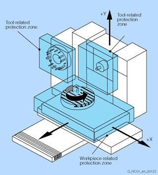
Protection zones
Protection zones allow you to protect various elements on the machine and its equipment, as well as the workpiece to be created, from incorrect movements.
Some of the elements that can be protected are, for example:
- Fixed machine components and built-on accessories (tool magazines, swiveling touch probes)
- Moving parts belonging to the tool (tool carriers)
- Moving parts belonging to the workpiece (mounting tables, clamps, spindle chucks, tailstocks)
For the elements to be protected, 2D or 3D protection zones are defined in the part program or via system variables.
These protection zones can be activated and deactivated in the part program. Protection zones must always be divided into workpiece-related and tool-related zones. During machining in JOG, MDA or AUTOMATIC mode, a check is always made to see whether the tool (or its protection zones) violate the protection zones of the workpiece.
Monitoring of the protection zones is channel-based, that is, all active protection zones for a channel are mutually monitored for collisions (protection zones not channel-specific with NCU system software for 2/6 axes).
A maximum of ten protection zones and ten contour elements, which describe a protection zone, are available.
Punching/nibbling (option M33)
The punching/nibbling functions are implemented essentially via the language commands, stroke control and automatic path division.
- Language commands
The punching/nibbling functions are activated and deactivated using simple, clear high-level language elements such as PON, SON, PONS, PDELAYON, and so on. - Stroke control
CNC and punch are synchronized to each other by the high-speed signals that are input and output via the drive bus in the control's position-control cycle, making it possible to attain high velocities and maximum precision. - Automatic path division
You can choose whether you want the control to break the machining path down automatically by stroke length (SPP) or stroke rate (SPN). With SPP, the travel path is broken down into programmable segments of identical size (modal effect). SPN breaks the travel path down into a programmable number of path sections (non-modal effect).
Quadrant error compensation
Quadrant transitions without compensation
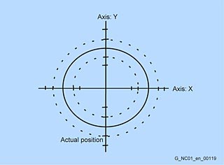
Quadrant transitions with quadrant error compensation
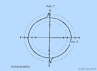
Quadrant error compensation (also referred to as friction compensation) ensures a much higher degree of contour precision, particularly when machining circular contours. At the quadrant transitions, one axis traverses at the maximum path velocity while the second axis is stationary. The different friction conditions can cause contour errors. Quadrant error compensation virtually eliminates this problem and produces excellent results, without contour errors, in the very first machining operation.
In operator-controlled quadrant error compensation, you set the intensity of the correction pulse as per an acceleration-based characteristic. This characteristic is determined and parameterized on startup with the aid of the circularity test. During the circularity test, deviations of the actual position from the programmed radius (particularly at the quadrant transitions) are recorded by measurement and graphically represented while the circular contour is being retracted.
Reference point approach
When using a machine axis in program-controlled mode, it is important to ensure that the actual values supplied by the measuring system agree with the machine coordinate values. Reference point approach (limit switch) is performed separately for each axis at a defined velocity either using the direction keys, in a sequence that can be defined in the machine data, or automatically via program command G74. If length measuring systems with distance-coded reference marks are used, reference point approach is shorter, as it is necessary to approach only the nearest reference mark.
Reference point approach of an axis with absolute-value encoders is carried out automatically when the control is switched on (without movement of axis), if the corresponding axis is recognized as being calibrated.
Repos
Following a program interruption in AUTOMATIC mode (e.g., to take a measurement on the workpiece and correct the tool wear values or because of tool breakage), the tool can be retracted from the contour manually after changing to JOG mode.
In this case, the control stores the interruption point coordinates and displays the differential travel of the axes in JOG mode in the actual-value window as a Repos (repositioning) offset.
The contour can be reapproached:
- In JOG mode using the axis and direction keys. It is not possible to overshoot the interruption point; the feedrate override switch is effective.
- By the program (with reference to the interruption block), either at the point of interruption, the start of the block, at a point between the start of the block and the interruption point, or at the end of the block. Modified tool offsets are taken into account. You can program approach movements as straight lines, in quadrants or in semicircles.
Representation (2D) of 3D protection zones/work areas
> Working area limitation; protection zones
You can use protection zones to protect various elements on the machine, their components and the workpiece against incorrect movements. The three-dimensionally programmed protection zones are displayed in 2D. This also applies to the programmed working area limitations.
Residual material detection (option P13)
Contour ranges which cannot be machined with large tools are automatically recognized by the cycle for contour pockets or the stock removal cycle. The operator can rework these regions using a smaller tool.
Contour turning offers:
- Contour/axis-parallel cutting with residual material detection
- Contour cutting with residual material detection
- Plunge-turning with residual material detection
Contour milling offers:
- Contour spigot with residual material detection
- Contour pocket with residual material detection
- Machining, e.g. in the steps: centering, predrilling, rough machining and rough machining residual material, smoothing, edge/base, gripping
Rotary axis, turning endlessly
Depending on the application, the working area of a rotary axis can be limited via a software switch (e.g., working area between 0° and 60°) or to a corresponding number of rotations (e.g., 1000°), or it can be unlimited (endlessly turning in both directions).
This function can also be used with absolute-value encoders.
Safety Integrated
SINUMERIK Safety Integrated are integrated safety functions that support the implementation of highly effective personnel and machine protection. The safety functions meet the requirements of DIN EN 61508 for use up to and including SIL 2 and Category 3, and PL d according to DIN EN ISO 13849. This allows the main requirements for functional safety to be implemented easily and cost-effectively. Available functions include, among others:
- Functions for safety monitoring of velocity and standstill
- Functions for establishing safe boundaries in work spaces and protected spaces, and for range recognition
- Direct connection of all safety-related signals and their internal logical linkage
Safety Integrated (option M63)
SI Basic function package (incl. 1 axis/spindle, up to 64 SPL I/Os) for one NCU.
Safety Integrated (option M64)
SI Comfort function package (incl. 1 axis/spindle, up to 64 SPL I/Os) for one NCU
Sag compensation, multi-dimensional (option M55)
Example: Sag compensation
Multidimensional compensation is also possible for the effects of physical influences and manufacturing tolerances such as sag or leadscrew pitch errors. The compensation tables can be switched from the PLC.
When the reference axis and the compensating axis are identical, leadscrew pitch errors can be compensated. By transferring weighting factors (PLC interface), stored compensating characteristics can be adapted to different conditions (e.g., tools).
The most important features of interpolation and compensation using tables are as follows:
- Independent error characteristics can be defined, in number twice the maximum number of axes
- Freely selectable compensating positions, the number of which is configurable (dependent on the configuration of CNC user memory)
- Interpolating inclusion of the compensation values
- Weighting factor for compensation of tool weights
- Reference axis and compensating axis are selectable
Limited functionality of export control versions:
The tolerance band that can be corrected is limited to 1 mm (0.039 in) (in standard control versions: 10 mm (0.39 in)).
SCIS transformation for pantograph kinematics (option)
"Pantograph" kinematic transformation is a type of 2-/4-axis transformation with parallel kinematics. It can work with fixed-length rods, or rods whose lengths can be modified.
When using kinematic transformations, workpieces can be programmed in Cartesian coordinates as usual. The SINUMERIK control calculates the required movements of the machine axes online. Therefore, the programmer can create part programs in the same way as on a conventional machine, and does not have to take the special kinematics of the machine into account.
Scratching, determining work offset
A work offset can also be determined through scratching, taking into consideration an (active) tool and, where applicable, the base offset, by moving the axis to the workpiece, entering the desired setpoint position (e.g. "0"), and the controller calculates the work offset.
Screen blanking
When screen blanking is activated, both the screen and backlighting of the operator panel go blank under PLC control or after a programmable period of time has elapsed. This increases the service life of the screens.
Separate path feed for corners and chamfers
To optimize solutions for machining tasks, a separate path feed can be programmed with FRCM (modal) or FRC (non-modal) for the corner and chamfer contour elements. Feed reduction thus makes it possible to achieve the desired geometrically precise definition of corners and chamfers.
Series machine startup
Files called series machine startup files can be generated to enable transfer of a particular configuration, in its entirety, to other controls that use the exact same software version, for example, controls that are to be used for the same machines. Series machine startup thus means bringing a series of controls to the same initial state as regards their data. You can archive/read selected CNC, PLC and PCU data for series machine startup. Compensation data can be optionally saved. The drive data are stored as binary data, and cannot be modified.
Series machine startups can even be performed readily and easily without a programming device. Simply create a startup file in the PCU, save it on a PC card in the control, insert this card in the next control, and begin the series machine startup procedure. Series machine startups can also be performed via a network drive or a USB stick.
Set actual value
The "Set actual value" function is provided as an alternative to the "Preset" function: To use this function, the control must be in the workpiece coordination system (WCS). With "Set actual value", the workpiece coordinate system is set to a defined actual coordinate and the resulting offset between the previous and a newly entered actual value computed in the WCS as 1st basic offset. The reference points remain unchanged.
Setpoint exchange (option M05)
Setpoint exchange is used on milling machines with special milling heads on which, for example, the spindle motor is used both for driving the tool and for orientation of the milling head. In this case, the spindle and the milling head axes are defined as independent axes in the control, but are traversed only in succession by one motor.
It is possible to connect up to 4 axes to one motor. The axes, which the setpoint switches between, can be assigned to different channels or mode groups.
ShopMill/ShopTurn (option P17)
The "ShopMill/ShopTurn" option includes the functions:
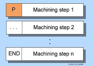
- Machining step programming
Machining step programming
Processes such as drilling, centering, plunging or pocket milling are represented as machining steps in a simple and clear manner. In this way part programs – even for complex machining operations – are very compact and easily read. Associated sequences are automatically interlinked and can be assigned any position patterns. This unique programming convenience allows you to achieve the shortest programming times even for highly demanding machining tasks.
SI axis/spindle, additional axis/spindle (option C71-C78)
One additional SI axis/spindle
SI axis/spindle package, additional 15 axes/spindles (option C61/C62)
Additional 15 SI axes/spindles)
Simulation
Simulation is supported by an autonomous program interpreter and a separate simulation data environment at HMI level. The simulation interpreter extensively considers the complete syntax of the SINUMERIK range of controls, including the possibility of incorporating special user options on the machine by comparing data with the NCK environment. The simulation data can be matched statically as required with the NCK environment (initialization data, macros, user data, tool data, machining cycles) or also dynamically when tool data or machining cycles are changed.
Machining simulations, with emphasis on drilling/milling and turning technologies, can be executed on the control's HMI in the workpiece coordinate system for certain machine kinematics depending on the active operating software (see also function overview) and its software version as follows:
Simulation (SINUMERIK Operate)
- 3D simulation 1 (option P25)
While a workpiece is being machined, machining of a different workpiece can be simulated. The finished part is simulated using the real data and the NC kernel. The NC data is automatically updated on every switchover to 3D simulation. 3D simulation on the NCU can be used from NCU 720.2 upwards.
Simulation (HMI Advanced)

Simulation drilling/turning with HMI Advanced

Simulation of turning with HMI Advanced
- Drilling/milling:
Simulation of multiface drilling and milling operations with display of material removal and/or displayable tool path line graphs. Simulation of removal is primarily designed for paraxial machining in a rectangular 3D workpiece space. Other kinematics which cannot be exactly represented with the 3D removal simulation, or machining operations based on incomplete tool data, can nonetheless provide informative approximations using the integral tool path simulation. - Turning complete machining:
Turning operations can be displayed here in side views as linear tool path graphics with dynamic updating of the blank envelope in the dynamically balanced 2 D workpiece space. Drilling and milling on the front face or on the peripheral surface of turned parts can be simulated with representation of the removed material and/or the tool path graphics with the same features as described under "Drilling/milling". Furthermore, display versions are available for variable machine arrangements (e.g. for turning in front of or behind the turning center, on the main spindle or counterspindle, for horizontal or vertical turning machine orientations).
In this manner, the simulation results in several part programs in succession can be superimposed in a complete representation on the same unmachined part (e.g. starting from preformed blanks, for multiface machining when milling, multi-slide and multi-spindle machining when turning etc.).The machined part finally originates from the sequential interaction of all individually simulated part programs. For turning, input of a length offset for rear-side machining with mirrored tools is possible, as well as input of CNC keywords for dynamic spindle changeover, e.g. for main spindle and counterspindle operation. Visualization of the simulation can be customized using parameterization screens in many areas. Graphics can be observed in various views and sections, in zoom representations, or in several windows simultaneously.
Simultaneous recording (option P23/P24)
During machining, the tool paths can be simultaneously recorded on the display of the controller in three-side view or in 3D view. Workpiece graphics and views correspond to the graphic simulation.
SINUMERIK MDynamics
Technology packages for 3-axis and 5-axis milling.
SINUMERIK MDynamics ensures perfect surfaces through innovative motion control and an optimized NC data compressor, rapid adaptation to the workpiece, tool and program handling, optimum machining thanks to the flexible programming of programGuide and ShopMill and, as a result, the shortest programming times.
- MDynamics 3 axes (option S32)
Contains the options:
ShopTurn/ShopMill, residual material detection and machining for contour pockets and cutting.
3D simulation 1 (finished part), simultaneous recording, advanced surface, spline interpolation, transmit and peripheral surfaces transformation and measuring cycles. - MDynamics 5 axes (option S33)
Contains the options:
ShopTurn/ShopMill, residual material detection and machining for contour pockets and cutting.
3D simulation 1 (finished part), simultaneous recording, advanced surface, spline interpolation, transmit and peripheral surfaces transformation and measuring cycles.
Machining package 5 axes, 3D tool radius compensation and measure kinematics.
SINUMERIK Operate programming package/SINUMERIK Operate runtime license OA programming (option P60)
The SINUMERIK Operate programming package allows SINUMERIK users to design their own user interfaces to visualize either machine-manufacturer or end-user functional expansions or simply their own screen form layouts.
User interfaces programmed by Siemens or other machine manufacturers can be modified or replaced. This function is realized in a high-level language development environment based on C++/QT that can generate a platform-independent execution code for Windows XP (SINUMERIK PCU 50.3) and Linux (NCU).
The screen forms are created platform-independently in the development environment.
The compiled program parts are transferred to the corresponding user directories of the PCU 50.3 or NCU.
Configuring examples for new screen forms, which can also be used as the basis for the user's own new screen forms, can be found on the product DVD of the SINUMERIK Operate programming package.
You can implement the following functions with the "SINUMERIK Operate programming package":
- Display screen forms and softkeys, variables, tables, texts, help texts, graphics, and help screens
- Start actions when screen forms are displayed and exited, press softkeys, and enter values (variables)
- Dynamically restructure screen forms, including changing softkeys, designing arrays and displaying, replacing and deleting display texts and graphics
- Read and write variables, combine with mathematical, comparative or logical operators
- Execute subprograms, file functions, program instance services (PI services) or external functions (SINUMERIK Operate)
- Enable data exchange between screen forms
The SINUMERIK Operate runtime license OA programming (option P60) is required for executing the programmed user screens.
SINUMERIK Operate runtime license OA Easy Screen (option P64)
The "Easy Screen" functionality allows SINUMERIK users to design their own user interfaces to visualize either machine-manufacturer or end-user functional expansions or simply their own screen form layouts.
User interfaces configured by Siemens or other machine manufacturers can be modified or replaced. This function is implemented via an integrated interpreter and via configuring files containing the description of the user interface.
The screen forms can be designed directly on the control itself. A graphic tool is required to create graphics and pictures. Part programs can be processed with newly created user interfaces.
Configuring examples for new screen forms, which can also be used as the basis for the user's own new screen forms, can be found in the supplied toolbox.
You can implement the following functions using "Easy Screen":
- Display screen forms and softkeys, variables, tables, texts, help texts, graphics, and help screens
- Start actions when screen forms are displayed and exited, press softkeys, and enter values (variables)
- Dynamically restructure screen forms, including changing softkeys, designing arrays and displaying, replacing and deleting display texts and graphics
- Read and write variables, combine with mathematical, comparative or logical operators
- Execute subprograms, file functions, program instance services (PI services) or external functions (HMI Advanced)
- Enable data exchange between screen forms
- Easy Screen is configured using ASCII files that can be stored on the PCU. Files that contain ASCII descriptions for the layout of interactive screen forms, softkey functions and display texts and graphics are interpreted. These configuring files are created with the ASCII editor, taking into account certain special rules of syntax.
With the integrated editor, even the basic version of the user interface can be expanded at predefined softkeys by up to 5 screens (more than 5 screens with Operate runtime license OA Easy Screen (option P64)).
Skip blocks
CNC blocks that are not to be executed in every program run, e.g., execute a trial program run, can be skipped. Skip blocks are identified by placing a "/" character in front of the block number. The instructions in the skip blocks are not executed and the program resumes with the next block that is not skipped.
As many as eight skip levels (/0 to /7) may be programmed. The individual skip levels are activated via a data block in the PLC interface.
Space compensation, VCS plus (option N17)
VCS plus is designed for use on large machines (3-axis and 5-axis gantry milling machines). The requirements for positioning accuracy of these machines in the complete work space (= volumetric accuracy) increases constantly and is specified in individual cases as < 50 µm.
The compile cycle "VCS plus" implements volumetric compensation of all 21 aspects of freedom from errors that the 3 basic axes of a cartesian machine tool can demonstrate (per axis: linearity, 2 degrees of error, rolling, pitching, swerving as well as deviations from the perpendicular between axes). These geometrical machine errors cause offsetting of the tool center point and an orientation error in the tool.
On a 5-axis machine, the tool center point and the orientation error of the tool are compensated with VCS plus with TRAORI active.
In comparison to LEC (leadscrew error compensation) and CEC (circle error compensation), VCS plus supports the total compensation of the geometric error of a cartesian machine tool. VCS plus can be superimposed on the previously set LEC and CEC values.
The geometric error of a machine tool is measured with external laser-based instruments that determine these errors as effectively as possible. The measured results are supplied to the SINUMERIK as a file in the specified readable VCS format.
Measurement of the machine error is the responsibility of the OEM or machine operator. Several SINUMERIK Solution Partners offer support and measurement as a service and they can generate the machine-specific VCS files necessary for VCS plus.
Space error compensation for kinematic transformations (option M57)
Space error compensation (SEC) is a method for compensating static position errors at the tool center point (TCP). In this way, these position errors can be compensated in the three directions in space (x, y and z) simultaneously. Measuring instruments are required for determining the error that allow the three coordinates of a measuring point to be recorded simultaneously at multiple points distributed throughout the working area (e.g. a 3D laser tracker). The SINUMERIK control can then use the resulting 3D error table to compensate each positioning window in real time.
Spindle functions
Spindle modes are:
- Open-loop control mode (constant spindle speed S or constant cutting rate G96)
- Oscillation mode
- Positioning mode
- Synchronous mode (synchronous spindle)
- Thread cutting/tapping
Functions of the spindle modes:
- Spindle speed with spindle override
- 5 gear stages, specified in the
- Part program (commands M41 to M45)
- Automatically via programmed spindle speed (M40) or
- PLC function block FC18
- Oriented spindle stop (positioning mode) with SPOS1)
- Spindle monitoring with the functions:1)
- Axis/spindle stationary (n <nmin)
- Spindle in set range
- Max. spindle speed
- Programmable lower (G25) and upper (G26) spindle speed limitation
- Min./max. speed of the gear stage
- Max. encoder limit frequency
- End point monitoring for SPOS
- Constant cutting speed with G96 (in m/min or inch/min) at the tool tip for uniform turning finish and thus better surface quality. Spindle control via PLC for oscillation (for easier engaging of a new gear stage) and positioning
- Switch to axis operation:
For machining with a position-controlled spindle (face machining of turned parts, for example), the main spindle drive can be switched to axis mode with a program command. A common encoder can be used for both axis and spindle modes. The zero mark of the spindle is also the reference mark of the C axis, so there is no longer any need to home the C axis (synchronize C axis on the fly). - Thread cutting with constant pitch:1)
With G33 you can produce the following thread types: cylindrical, taper and face thread, single-start or multiple-start, as left-hand or right-hand thread. In addition, multiple-block threads can be produced by concatenating threading blocks. - Thread cutting with variable pitch:1)
Threads can also be programmed with linearly progressive (G34) or linearly degressive (G35) pitch. - Programmable run-in and run-out of thread:
When thread cutting, you can use DITS/DITE (displacement thread start/end) to program the path ramp for the acceleration or deceleration process as a displacement. This makes it possible, for example, to adjust the acceleration on the thread shoulder when the tool run-in or run-out is too short and initiate smoothing at the next CNC start. - Tapping with compensating chuck/rigid tapping:
When tapping with compensating chuck (G63), the compensating chuck equalizes differences between spindle movement and drilling axis. A prerequisite for rigid tapping (G331/G332) is a position-controlled spindle with position measuring system. The traversing range of the drilling axis is therefore not restricted. By using the method whereby the spindle, as a rotary axis, and the drilling axis interpolate, threads can be cut to a precise final drilling depth (e.g., for blind hole threads).
1) Prerequisite: actual-position sensor (measuring system) with corresponding resolution (mounted directly on the spindle).
Spindle speed limitation
> Spindle functions
Spline interpolation
- Spline interpolation for 3-axis machining (option M16)
- Spline interpolation for 5-axis machining (option M17)
- Spline interpolation (option S16)
By using spline interpolation it is possible to obtain a very smooth curve from just a few defined interpolation points along a set contour. The intermediate points are connected by polynomials. The compressor converts linear motions (e.g., from CAD) at block transitions to splines of constant speed (COMPON) or splines of constant acceleration (COMPCURV). This yields soft transitions that reduce wear on the mechanical parts of the machine tool. However, if the intermediate points are placed close together, quite sharp edges can also be programmed. Spline interpolation also considerably reduces the number of program blocks required.
Extremely smooth workpiece surfaces are often very important in mold and tool making, both optically and technologically, e.g., for rubber gaskets.
Tool radius compensation is also possible in spline interpolation, as it is in linear or circular interpolation.
Every polynomial can represent a spline. Only the algorithm determines the type of spline.
- A spline is only true to the tangents.
- B spline is true to the tangents and the curvature, but does not run through the nodes (intermediate points).
- C spline is true to the tangents and the curvature and runs through the nodes.
With the COMPCAD compressor, such "smooth" curves can be approximated within the boundaries of compressor tolerance (parallel tool paths) and surfaces of a high optical quality can also be obtained in the case of large tolerances.
Spline interpolation for 3-axis machining is suitable for simple applications and for the JobShop area.
Standstill monitoring
> Position monitoring
Standstill monitoring represents one of the most comprehensive mechanisms for monitoring axes. The monitor checks to see whether the following error has reached the standstill tolerance limit following the elapse of a programmable time period. Upon termination of a positioning action, standstill monitoring takes over from position monitoring, and checks to see whether the axis moves further from its position than stipulated in the machine data's standstill tolerance field. The standstill monitoring function is always active following expiration of the zero speed delay time or upon reaching the fine exact stop limit as long as no new traversing command is pending.
When the monitor responds, an alarm is generated and the relevant axis/spindle brought to standstill with rapid stop via a speed setpoint ramp. Standstill monitoring is effective for linear and rotary axes as well as for position-controlled spindles. Standstill monitoring is inactive in follow-up mode.
Subprogram levels and interrupt routines
Subprograms can be called not only in the main program, but also in other subprograms. Subroutines can be nested to a depth of 12 levels, including the main program level. This means that a main program may contain as many as 11 nested subroutine calls. When working with Siemens cycles, three levels are required. If such a cycle is to be called from a subprogram, the call can be nested at a depth of no more than 9 levels.
Programs can also be called on the basis of events following resetting of the part program start or end, or following booting of the control. Users can then make the basic function settings or carry out initializations using a part program command.
A system variable can be used to scan the event, which activated the associated program.
Synchronized actions stage 2 (option M36)
More than 24 synchronous actions can be active in the CNC block. As many as 255 parallel actions can be programmed in each channel. Technology cycles can be combined into programs using synchronized actions stage 2, making it possible, for example, to start axis programs in the same IPO cycle by scanning digital inputs.
Limited functionality of export control versions:
The number of simultaneously traversed axes is limited to 4 (path and positioning axes).
Synchronous actions
> Cross-mode actions
Even in its basic configuration, SINUMERIK allows you to initiate up to 24 actions synchronous to the axis and spindle movements. These actions run in parallel with workpiece machining, and their inception can be determined on the basis of conditions. The starting of such motion-synchronous actions (or synchronous actions for short) is, therefore, not restricted to CNC block boundaries.
Synchronous actions are always executed in the interpolation cycle. Several actions can even be carried out in the same IPO cycle.
Synchronous actions without validity identifier are non-modal only in AUTOMATIC mode. Synchronous actions with validity identifier ID are modal in the subsequently programmed blocks in AUTOMATIC mode. Statically effective synchronous actions with the identifier IDS remain active in all modes ("Cross-mode actions").
Synchronous actions provide you with an excellent programming tool to respond very quickly to events in the interpolation cycle. Here are some typical applications:
- Comparison operation-dependent or external signal-dependent transfer of auxiliary functions M and H to the PLC user software and derived machine responses
- Fast, axis-specific, input signal-based deletion of the residual distance
- External signal-controlled read-in disable for the CNC block
- Monitoring of system variables such as velocity, power and torque
- Controlling process variables (velocity, speed, distance, etc.)
Limited functionality of export control versions:
Only 1 active synchronous function (SYNFCT) is possible at a time. The number of simultaneously traversed axes is limited to 4 (path and positioning axes).
Synchronous spindle/multi-edge turning (option M14)
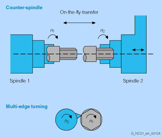
Examples for synchronous spindles/multi-edge turning
True-to-angle synchronization of one leading and one or more following spindles enables on-the-fly workpiece transfer, particularly for turning machines, from spindle 1 to spindle 2, for example for the purpose of finishing, without experiencing the non-productive times normally associated with rechucking.
In addition to the speed synchronism, the relative angular position of the spindles to one another, e.g., on-the-fly, position-oriented transfer of edged workpieces, is also specifiable.
On-the-fly transfer:
- n 1 =n2
- Angle 1 = angle 2 or
- Angle 2 = angle 1 + angle
Finally, specification of an integer speed ratio between the main spindle and a tool spindle provides the prerequisites for multi-edge machining (polygon turning).
Multi-edge turning:
n 2 = T · n1
Configuring and selection take place either via the CNC program or the operator panel. Several pairs of synchronous spindles can be implemented.
Tangential control (option M06)
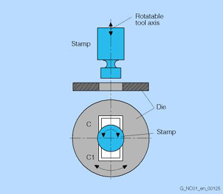
Representation of a rotatable tool axis and die during punching/nibbling
Tangential control makes it possible to correct a rotary axis in the direction of the tangents of two path axes. The two leading axes and the corrected axis lie in the same channel.
Applications:
- Tangential setting of a rotatable tool during punching/nibbling
- Correction of the workpiece alignment for a belt saw
- Setting of a dressing tool on a grinding wheel
- Tangential feed of a wire for 5-axis welding
- Setting of a cutting wheel for machining glass or paper
Tangential control is effective in all interpolation modes.
On punching and nibbling machines with a rotatable punching tool and associated lower tool, the following functions may be used to ensure universality of the tool:
- Tangential control
TANGON/TANGOF for vertical rotary axis alignment of the punching tool to the direction vector of the programmed path - Coupled motion
TRAILON/TRAILOF for synchronous rotation of upper and lower tool (stamp and die)
Tapping with compensating chuck/rigid tapping
> Spindle functions
Technology cycles

Example: Swiveling to any surface
Example: Milling the circular pocket
For frequently repeated machining tasks, technology cycles are available for the drilling/milling and turning technologies.
Technology cycles are generally applicable technology subprograms, with which specific machining processes can be implemented, such as tapping a thread or milling a pocket. The cycles are adapted to a concrete machining task by means of parameters. The parameterization can also be implemented using graphically supported input screens.
- Drilling:
Drilling/centering, drilling/counterboring, deep-hole drilling, tapping with and without compensating chuck, boring 1 ... 5, row of holes/circle of holes, grid of holes, machining on inclined surfaces - Milling:
Thread milling, elongated holes in a circle, groove in a circle, circumferential groove, rectangular/circular pocket, face milling, path milling, rectangular/circular spigot, machining on inclined surfaces, high-speed settings for optimized HSC machining, engraving cycle - Turning:
Groove, undercut, cutting with relief cut, thread undercut, thread cutting, chaining of threads, thread recutting
Temperature compensation
Heat causes machine parts to expand. This expansion depends, among other things, on the temperature and on the thermal conductivity of the machine parts. The actual positions of the individual axes, which change on the basis of variations in temperature, have a negative effect on the precision with which workpieces are machined. These actual value modifications can be corrected using temperature compensation.
At a specific temperature, measure the actual-value offset over the positioning range of the axis to obtain the error curve for this temperature value. Error curves for different temperatures can be defined for each axis.
In order to ensure proper compensation of thermal expansion in changing temperatures, the temperature compensation value, reference position, and linear angle of lead parameters must be transferred from the PLC to the CNC via function blocks each time the temperature changes. Abrupt changes in these parameters are automatically smoothed by the control in order to prevent machine overload and avoid triggering watchdog monitors unnecessarily.
Thread cutting
> Spindle functions
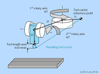
Tool carrier with orientation capability
Kinematics type T
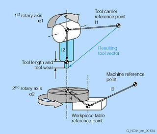
Kinematics type M
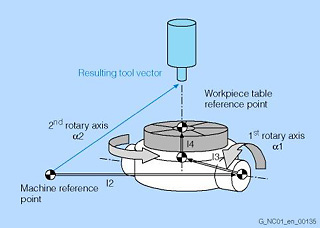
Kinematics type P
For machine tools, which have tool carriers with settable tool orientation, the user of a SINUMERIK control can freely configure these kinematics without using 5-axis transformation. The "tool carrier with orientation capability" function enables 2 D/3D machining with fixed spatial orientation of the tool/workpiece table.
Vectors l1 to l4 represent the geometrical dimensions of the machine. The rotary axes need not move in parallel to the Cartesian axes, but instead can be inclined at any angle (e.g., cardan milling head with 45° inclination).
The angles1 and2 can be either specified or computed from the active frame and assigned to the tool carrier with orientation capability or to the workpiece table.
The following kinematics can be configured flexibly:
- Rotatable tool: type T (tool)
- Rotatable tool/rotatable workpiece table: type M (mixed)
- Rotatable workpiece table: type P (part)
Tool change via T number
In chain, rotary-plate and box magazines, a tool change normally takes place in two stages: A T command locates the tool in the magazine, and an M command inserts it in the spindle. In circular magazines on turning machines, the T command carries out the entire tool change, that is, locates and inserts the tool. The tool change mode can be set using machine data.
Tool identification systems
The Siemens Tool Management tool load and unload dialog boxes offer a link to an automatic tool identification system. This allows you to replace manual input of the tool data with automatic reading and writing of the tool code carrier.
During unloading, the data block for the tool is saved; during loading, it is read via the code carrier and entered in the tool management. In the interim, the tool data can be re-edited as during tool selection from the tool catalog (offset data, etc.).
Using an editable description file containing precisely defined tool and cutting data, the code carrier data are converted during loading into dialog data, which can be read by the tool management. During unloading, the dialog data are converted back into code carrier data with the aid, once again, of the description file.
Tool management (option M50)
Tool management ensures that the correct tool is in the correct location on the machine at any given time and that the data assigned to the tool are up to date. Tool management is used on machine tools with circular magazines, chain magazines or box magazines. It also allows fast tool changes and avoids both scrap by monitoring the tool service life and machine downtimes by using spare tools.
The most important functions of tool management are:
- Tool selection throughout all magazines and turrets for active tools and spare tools
- Ascertaining of a suitable empty location depending on tool size and location type
- Tool-dependent location coding (fixed and variable)
- Initiation of tool changes with T or M command
- Axis movements during a tool change with automatic synchronization when next D number is encountered
- Quantity and tool life monitoring with prewarning limit monitoring function
Missing tools can be loaded based on a decision made by the operator. Tools with similar wear characteristics can be combined into wear groups.
Tool management also takes tool length compensations for adapters that are permanently mounted at certain magazine locations and fitted with different tools into account.
Tool management with more than 3 magazines (option M88)
In the basic version of the SINUMERIK 840D sl, 3 magazines (magazine, spindle, tool buffer) are included. With option M88, the number of magazines can be increased.
Tool offsets
Tool offsets
By programming a T function (5-figure integer number) in the block, you can select the tool. Every T number can be assigned up to 12 cutting edges (D addresses). The number of tools to be managed in the control is set at the configuration stage. A tool offset block comprises 25 parameters, e.g.:
- Tool type
- Up to three tool length offsets
- Radius compensation
- Wear dimension for length and radius
- Tool base dimension
The wear and the tool base dimension are added to the corresponding offset.
When writing the program, you need not take tool dimensions such as cutter diameter, cutter position or tool length into account.
You program the workpiece dimensions directly, following the production drawing, for example. When a workpiece is produced, the tool paths, depending on the relevant tool geometry, are controlled so that the programmed contour can be produced with every tool used.
You enter the tool data separately in the control's tool table, and in the program you call only the required tool with its offset data. During program execution, the control fetches the required offset data from the tool files and corrects the tool path for various tools automatically.
Tool offset D can be programmed with reference to tool number T (when the Siemens tool management is active, e.g., with monitoring functions and management of sister tools) or without internal references to existing tools.
You can define as many as 32,000 D values per control. D numbers can be freely assigned, checked, renamed, ascertained with the associated T number, invalidated, and activated on a site-dependent basis during programming.
Tool offsets, grinding-specific
> Grinding wheel surface speed
Grinding-specific tool offsets are available (minimum wheel radius, maximum speed, maximum surface speed, etc.) for grinding technology. When a cutting edge is created for grinding tools (tool type 400 to 499), these are stored automatically for the tool in question.
Tool types are:
400: Surface grinding wheel
401: Surface grinding wheel with monitoring
403: Surface grinding wheel with monitoring and without tool base dimensions for grinding wheel surface speed
410: Facing wheel
411: Facing wheel with monitoring
413: Facing wheel with monitoring and without tool base dimensions for grinding wheel surface speed
490 to 499: Dresser
With the TMON command, you can activate geometry and speed monitoring for grinding tools (type 400 to 499) in the CNC part program. Monitoring remains active until deactivated in the part program with TMOF. The current wheel radius and the current wheel width are monitored. The speed setpoint monitoring is monitored cyclically in relation to the speed limit value, taking into consideration the spindle override.
The speed limit value is the smaller of the values resulting from comparison of the maximum speed with the speed computed from the maximum grinding wheel surface speed and the current wheel radius.
Tool orientation interpolation
> Transformation, generic
Interpolations of tool orientations supplement generic transformation: The tool orientation can be programmed in a plane as large circle interpolation (ORIPLAN program command), on the outside surface of a taper in the clockwise or counterclockwise direction (ORICONCW/ORICONCCW), or even with free definition of the tool curve orientation (ORICURVE).
Tool radius compensation
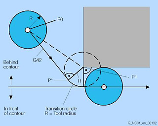
KONT for behind the contour
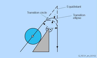
Bypassing the outside corners with transition circle/transition ellipse
When tool radius compensation is enabled, the control automatically computes the equidistant tool paths for different tools. To do so, it requires the tool number T, the tool offset number D (with cutting edge number), the machining direction G41/G42, and the relevant working plane G17 to G19.
The path is corrected in the programmed level depending on the selected tool radius. You can match the approach and retract paths to the required contour profile or rough-part forms, for example:
- NORM
The tool travels directly in a straight line to the contour, and is vertically aligned to the path tangent at the starting point. - KONT
If the starting point is behind the contour, the corner point P1 of the contour is bypassed. If the starting point is in front of the contour, in NORM the normal position at the starting point P1 is approached.
In the part program it is also possible to select the strategy with which the outside corners of the contour are to be bypassed:
- With transition radii (circle or ellipse)
- Intersection of equidistant paths
For soft approach to/retraction from the contour, i.e., tangential approach and retraction irrespective of the position of the starting point, various strategies are available: Approach and retract from left or right, on a straight line, on a quadrant or semicircle, in space or in the plane.
The control can also automatically insert a circle or a straight line in the block with the tool radius compensation when no intersection with the previous block is possible.
The offset process of tool radius compensation may be interrupted only by a certain number of successive blocks or M commands containing no motion commands or positional data in the compensating plane.
This number of successive blocks (or M commands) can be set using machine data (standard 3, max. 5).
3D tool radius compensation (option M48)
Inclined surfaces can be machined with 3D tool radius compensation or tool offset in space. This function supports circumferential milling and face milling with a defined path. The inclined tool clamping position on the machine can be entered and compensated. The control computes the resulting positions and movement automatically. The radius of a cylindrical milling cutter at the tool insertion point is included in the calculation.
The insertion depth of a cylindrical milling cutter can be programmed. The milling cutter can be turned not only in the X, Y and Z planes, but also by the lead or hitch angle and the side angle.
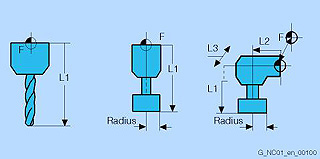
Tool types
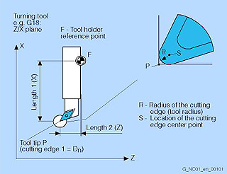
Geometry of turning tool
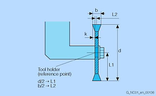
Geometry of slotting saw
The tool type determines the geometry specifications required for the tool offset memory, and how they are to be used. Entries are made for the relevant tool type in tool parameter DP. The control combines these individual components to produce a result variable (e.g., total length, total radius). The relevant overall dimension goes into effect when the offset memory is activated. The use of these values in the axes is determined by the tool type and current machining plane G17, G18 or G19.
The following tool types can be parameterized:
Group 1xy: milling cutters (from spherical head cutter to bevel cutter)
Group 2xy: drills (from twist drill to reamer)
Group 4xy: grinding tools (from surface grinding wheel to dresser)
Group 5xy: turning tools (from roughing tool to threading tool)
Group 700: slotting saw
The saving of all tool offsets is supported by input screens.
For wood technology, the slotting saw tool is available as a tool type.
Transformation, generic
Generic transformation is used to define any tool orientation in space with the initial state of the axes, and not just according to the Z direction. It can then be used much more flexibly and universally.
It is then possible to also control machine kinematics by the CNC where the orientation of the rotary axes is not exactly parallel to the linear axes. Generic 5-axis transformation has been extended to 3-axis and/or 4-axis transformation, i.e., it can also be used for machines with only one rotary axis (rotatable tool or workpiece).
Transformation package for handling, RCTRA (option M31)
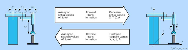
Transformation package Handling
The transformation package for handling contains the so-called standard transformation block, with whose help typical 2-axis to 5-axis handling devices such as gantries or SCARAs can be operated. This coordinate transformation package converts the axis-specific actual values for the axes (e.g., A1 to A4) into Cartesian values (e.g., X, Y, Z, A) and the programmed Cartesian setpoints back into axis-specific values for the handling devices.
Thanks to this coordinate transformation, the movements of the handling device become simpler and more user-friendly. The handling device can be set up, that is, manually traversed not only in the axis-specific coordinate system, but also in the Cartesian coordinate system of the handling device, using, for example, the jog keys on the handheld programming unit. Adaptation of the respective kinematics is carried out via machine data.
A 6-axis transformation for defined applications is also available on request.
Limited functionality of export control versions: Not possible.
Transformation HEXAPOD (option)
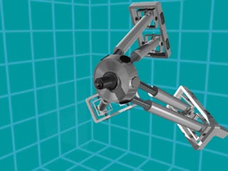
HEXAPOD animation
Transformation PARACOP (option)
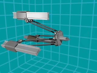
PARACOP animation
Transformation TRICEPT (option)
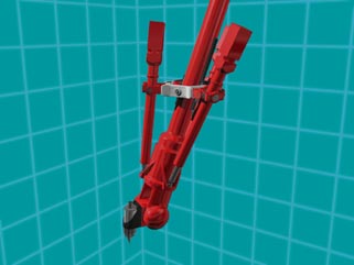
TRICEPT animation
HEXAPOD, PARACOP, TRICEPT kinematic transformations and pantograph kinematics are used on parallel-kinematics machines (PKM). Parallel kinematics means that the drive forces engage on the spindle head (Stuart platform) simultaneously (virtually in parallel).
With HEXAPOD, the Stuart platform is moved by six actuators, whose lengths can be modified. The Stuart platform can be moved to any position, including within the working area, by these six actuators, and its inclination in space (orientation) can also be set specifically. This allows workpieces to be machined on 5 axes on these machines. The orientation angle is only limited by the mechanical properties of the cardan or ball joints.
PARACOP and TRICEPT machines are TRIPODEN types, whereby the Stuart platform is moved by three actuators. Design measures are used to ensure that the Stuart platform cannot move in an undefined manner on these TRIPODEN types. On PARACOP machines, two parallel rods run on a slide for each actuator. These machines are suitable for 3-axis machining. On TRICEPT, an additional passive telescope (center tube) is used. On TRICEPT, two additional rotary axes are required to define the tool orientation in space. These axes can be arranged as with a fork head on a 5-axis machine, for example, thus the design allows the machine to carry out 5-axis machining.
Transformation TRIPOD HYBRID Kinematic (option)
This kinematic transformation (THYK) is a 5-axis transformation for 3 parallel linear axes and two rotary axes (see parallel kinematic type Exechon). The tool movements are programmed complete with their orientation in the same manner as the cartesian 5-axis machine. The real-time transformation calculates the necessary paths and speeds for the real machine axes.
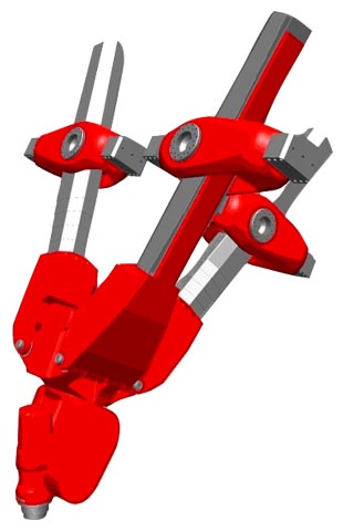
Parallel kinematic type Exechon
TRANSMIT/peripheral surface transformation (option M27)
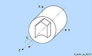
Face machining with TRANSMIT
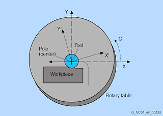
Tool-center-point path through the pole
TRANSMIT is used for milling outside contours on turned parts, e.g., square parts (linear axis with rotary axis).
As a result, programs become much more simple and complete machining increases machine efficiency. Turning and milling can be performed on one machine without rechucking.
3D interpolation with two linear axes and one rotary axis is possible. The two linear axes are mutually perpendicular and the rotary axis lies at right angles to one of the linear axes.
TRANSMIT can be called up in different channels simultaneously. The function can be selected and deselected with a preparatory function (straight line, helix, polynomial and activating tool radius compensation) in the part program or MDA.
With TRANSMIT, the area of the transformation pole is reached when the tool center can be positioned at least to the turning center of the rotary axis entering the transformation.
TRANSMIT through the pole is implemented in different ways:
- When traveling through the pole, the rotary axis is turned automatically by 180° when the turning center is reached and the remaining block is then executed.
- When traveling close by the pole, the control automatically reduces the feedrate and the path acceleration.
- If the path contains a corner in the pole, the position jump in the rotary axis is compensated by the control through automatic block insertion.
Peripheral surface transformation is used on turning machines and milling machines, and enables peripheral surface transformation, e.g., for turned parts.
The TRACYL peripheral surface transformation or cylinder surface transformation can be used to manufacture grooves of any shape on the surface of cylindrical bodies with or without groove side offset. The shape of the grooves is programmed in reference to the plane cylinder surface processed.
Travel to fixed stop
With this function, tailstocks or sleeves, for example, can be traversed to a fixed stop in order to clamp workpieces. The pressure applied can be defined in the part program. Several axes can be traversed to a fixed stop simultaneously and while other axes are traversing.
Travel to fixed stop with Force Control (option M01)
The "extended travel to fixed stop" function can be used to adapt torque or force on a modal or non-modal basis; travel with limited torque/limited force (force control, FOC) can be initiated, or synchronous actions can be used at any time to program traversing functions.
Traversing range
The range of values for the traversing ranges depends on the selected computational resolution. When the default value is specified in the machine data field "Computational resolution for linear or angular position" (1,000 increments per mm or degree), the ranges of values specified in the table can be programmed with this resolution:
|
G70 [inches, degrees] |
G71 [mm, degrees] |
|
|---|---|---|
|
Linear axes X, Y, Z, etc. |
± 399999,999 |
± 999999,999 |
|
Rotary axes A, B, C, etc. |
± 999999,999 |
± 999999,999 |
|
Interpolation parameters I, J, K |
± 399999,999 |
± 999999,999 |
If the computational resolution is increased/decreased by a factor of 10, then the value ranges change accordingly. The traversing range can be restricted by software limit switches and operating ranges.
Universal interpolator NURBS
Internal motion control and path interpolation are performed using NURBS (non-uniform rational B splines). This provides a uniform method for all internal interpolations that can also be used for future complex interpolation tasks.
The following input formats are available irrespective of the internal structure:
Linear, circular, helical, involute interpolation, splines (A, B, C) and polynomials.
User interface
The user interface has a clear layout with 8 horizontal and 8 vertical softkeys. The targeted use of Windows-type technology permits simple and user-friendly operation of the machine.
The interface is subdivided into 6 operating areas:
- Machine
- Parameters
- Program
- Services
- Diagnostics
- Startup
In this way, it is possible, for example, to create another part program while parts production is in progress and to transfer data from an external storage unit at the same time. On changing the operating area, the last active menu is always stored. There are two hotkeys for switching between operating areas.
User interface expansion
> SINUMERIK Operate Easy Screen
User machine data
The NCK makes machine data available for configuring the PLC user program. These user machine data are stored in the NCK-PLC interface during control power-up, prior to PLC power-up. The PLC basic program reads these data from the NCK-PLC interface during its initialization phase. This means that specific machine configurations, machine expansions and user options can be activated.
Variables and arithmetic parameters
Using variables in place of constant values permits the development of flexible programs. Variables make it possible to respond to signals, e.g. measured values. If variables are used as a setpoint value, the same program can be used for different geometries.
Variable types
|
The control uses 3 classes of variable: |
|
|---|---|
|
User-defined variable |
Name and type of variable defined by the user, e.g. arithmetic parameter |
|
Arithmetic parameters |
Special, predefined arithmetic variable whose address is R plus a number. The predefined arithmetic variables are of the REAL type. |
|
System variables |
Variables provided by the control that can be processed in the program (write, read). System variables enable access to work offsets, tool offsets, actual values, measured axis values, control conditions, etc. |
Variable types
|
Type |
Meaning |
Value range |
|---|---|---|
|
INT |
Integers with sign |
±(231 - 1) |
|
REAL |
Real numbers (fractions with decimal point, LONG REAL in acc. with IEEE) |
±(10-300 ... 10+300) |
|
BOOL |
Boolean values: TRUE (1) and FALSE (0) |
1.0 |
|
CHAR |
ASCII character specified by the code |
0 ... 255 |
|
STRING |
Character string, number of characters in [...], maximum of 200 characters |
Sequence of values with 0 ... 255 |
|
AXIS |
Axis names (axis addresses) only |
Any axis identifiers in the channel |
|
FRAME |
Geometrical parameters for moving, rotation, scaling, and mirroring |
Velocity
The maximum path and axis velocity and spindle speed are affected by the machine and drive dynamic response and the limit frequency of actual-value acquisition (encoder limit frequency and limit frequency of the input circuit). The resulting velocity from the programmed path length in the CNC block and interpolation cycle (IPO cycle) is always limited to the maximum velocity or, in the case of short path lengths, reduced to the velocity that can be travelled during one IPO cycle.
The minimum velocity must not go below 10-3 units/IPO cycle. The minimum and maximum axis velocities are dependent on the selected computational resolution. The maximum velocity of the axis is generally limited by the mechanics or by the limit frequency of the encoder or actual-value acquisition. The velocity value range is not limited by the CNC (max. 300 m/s).
Vibration extinction "VIBX" (option N11)
The function is implemented as a loadable compile cycle and supports the axis-specific damping of machine vibrations. Up to 8 axes can be parameterized in the CNC, each with 2 machine data for the filter frequency and the required damping factor. The function can significantly reduce disturbing oscillations that follow positioning actions.
Work offsets
> Frame concept
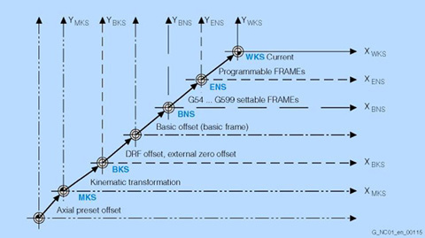
Coordinate system
According to DIN 66217, clockwise, rectangular (Cartesian) coordinate systems are used in machine tools.
The following coordinate systems are defined:
- Machine coordinate system MCS
The machine coordinate system is formed by all the available physical machine axes. - Basic coordinate system BCS
The basic coordinate system consists of three Cartesian axes (geometry axes), as well as other non-geometric axes (special axes). - BCS and MCS are always in
conformance when the BCS can be mapped to the MCS without kinematic transformation (e.g., TRANSMIT/interfacial transformation, 5-axis transformation and max. three machine axes). - Basic zero system BZS
DRF offsets, external work offsets and basic frames map the BCS on the BZS. - Settable zero system SZS
An activated settable work offset G54 to G599 transfers the BZS to the SZS. - Workpiece coordinate system WCS
The programmable frame determines the WCS representing the basis for programming.
Thus, you use work offsets to transform your machine zero point into the workpiece zero point in order to simplify programming. You can choose from among various work offsets:
- Settable work offsets:
You can enter offset coordinates, angles and scaling factors in up to 100 possible work offsets (G54 to G57, G505 to G599), in order to call zero points from any program for various fixtures or clamping operations, for example. The work offsets can be suppressed block-by-block. - Programmable work offsets:
Work offsets can be programmed with TRANS (substitution function, basis G54 to G599) or ATRANS (additive function). This allows you, for example, to work with different work offsets for repetitive machining operations at different positions on the workpiece. G58/G59 make previously programmed work offsets axially replaceable. - External work offsets:
You can also activate axis-related linear work offsets via the PLC user software (function blocks) with assignment of system variable $AA_ETRANS [axis].
Working area limitation
> Work offsets
Working area limitations describe the area in which machining is permitted.
These limitations refer to the basic coordinate system BCS. Checks are made to see whether the tool tip has penetrated the protected working area (also taking into account the tool radius). One value pair (plus/minus) per axis may be used to describe the protected working area.
The upper and lower working area limits, which can be set and activated via setting data, may be modified using the G25/G26 commands. Working area limitations restrict the traversing range of the axes in addition to the limit switches. Protective zones in which tool movements are suspended and which protect equipment such as tool turrets, measuring stations, etc., against damage, are thus set up in the machine's working area.
Working plane
> Tool radius compensation
When specifying the working plane in which the desired contour is to be machined, the following functions are defined at the same time:
- Plane for the tool radius compensation
- Infeed direction for the tool length compensation depending on the type of tool
- Plane for the circle interpolation
When calling the tool path correction G41/G42, the working plane must be defined so that the control can correct the tool length and radius.
In the basic setting, the working plane G17 (X/Y) is preset for drilling/milling, and G18 (Z/X) for turning.
Zero offsets
> Work offsets