
Acceleration with jerk limitation
To achieve an optimum acceleration pattern with reduced wear on the machine's mechanical parts, you can select SOFT in the part program to ensure a continuous, jerk-free acceleration profile. When you select acceleration with jerk limitation, the speed characteristic over the path is generated as a bell-shaped curve.
Access protection
|
Protection level |
Type |
PLC |
User |
Access to (examples) |
|---|---|---|---|---|
|
0 |
Password |
– |
Siemens |
All functions, programs, data |
|
1 |
Password |
– |
Machine manufacturers: |
Defined functions, programs and data (options) |
|
2 |
Password |
– |
Machine manufacturers: |
Defined functions, programs and data (machine data) |
|
3 |
Password |
– |
End user: |
Assigned functions, programs and data |
|
4 |
Red key |
7 |
End user: |
< Protection level 0-3 |
|
5 |
Green key |
6 |
End user: |
< Protection level 0-3 End users |
|
6 |
Black key |
5 |
End user: |
Program selection only, |
|
7 |
Switch position 0 |
4 |
End user: |
No input and program selection possible, only the machine control panel can be operated |
Access to programs, data and functions is protected in a user-oriented hierarchical system of eight access levels.
These are subdivided into:
- 4 password levels (protection levels 0 to 3) for Siemens, machine manufacturers and end users, and
- 4 keyswitch positions (protection levels 4 to 7) for end users (keyswitch positions can also be evaluated via PLC).
SINUMERIK controls thus provide a multi-level concept for controlling access rights.
Protection level 0 has the highest, protection level 7 the lowest access rights. A higher protection level automatically includes all protection levels below it. Access rights for protection levels 0 to 3 are preprogrammed by Siemens as standard.
An entered password takes precedence over a keyswitch position, and machine manufacturers or end users can change access rights for protection levels 4 through 7.
Subprograms can be protected in their entirety against unauthorized reading and displaying.
Action log
The action log (tachograph) records all operator actions and pending alarms for diagnostics purposes.
Actual-value system for workpiece
The term "actual-value system for workpiece" is used to designate functions, which allow the SINUMERIK user to:
- begin machining in a workpiece coordinate system defined via machine data in JOG and AUTOMATIC mode without any additional manipulations after powering up the control
- retain the valid settings relating to active level, settable frames (G54-G57), kinematic transformations, and active tool compensation at the end of the part program for use in the next part program
- toggle between the workpiece coordinate system and the machine coordinate system
- change the workpiece coordinate system (e.g., by changing the settable frames or tool offset)
Advanced Position Control (APC) (option M13)
The natural frequency of the machine can have a detrimental effect on the maximum speed of the machine and the surface characteristics. The Advanced Position Control (APC) function raises the KV factor, improves the surface and therefore increases productivity.
Advanced Surface (option S07)
The Advanced Surface function is used to optimize the motion control. Accurate contours and perfect surfaces can be achieved even at high machining speeds. With optimized speed management, Advanced Surface delivers better workpiece surfaces at high workpiece output rates.
Alarms and messages
Programming and displaying message texts
- Alarms and messages:
All messages and alarms are output separately on the operator panel in plain text with the date and time and a symbol indicating the cancel criterion. All alarms are saved in an alarm log that can be configured according to size. - Alarms and messages in the part program:
Messages can be programmed to give the operator information on the current machining situation during the program run. Message texts may be up to 124 characters long, and are displayed in two lines (of 62 characters each). The contents of variables can also be displayed in message texts.
Example 1:
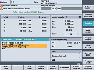
N10 G1 F2000 B=33,333
N15 MSG ("Rotary table position: "«$AA_IW[B]« "Degrees")
Display in message line following traversal of block N10:
Rotary table position: 33,333 degrees
Example 2:
N20 MSG ("X-position" »$AA_IW[X]« "Check!")
Display: X-position ... Check!
In addition to programming messages, you can also set alarms in a CNC program. An alarm always goes hand in hand with a response from the control according to the alarm category.
You will find a list of responses to the various alarms in the Startup Guide. The alarm text must be configured. Alarm numbers 65000 to 67999 are reserved for the user.
Example 3:
N100 SETAL (65001) Effect:
Display CNC start interlock
Delete: with Reset
- Alarms and messages from the PLC:
Machine-specific alarms and messages from the PLC program can be displayed as plain text. Messages comprise status messages and error messages. Whereas the display of a status message is immediately deleted when the condition is no longer active, error messages must always be acknowledged. Application-specific alarm numbers in the range 40000 to 89999 can be assigned to general, channel-specific, axis-specific and spindle-specific application alarms and messages. The response of the control to alarms or messages can be configured. The configured alarm and message texts are saved in application-specific text files. - Specific evaluation of alarms:
A channel-specific signal can be used to decide whether other channels may continue to be used when an alarm is issued.
Analog value control
System variable $A_OUTA(n) enables values from up to eight analog outputs to be preset directly in the part program. They are output via a SIMATIC DP ET 200 analog module. The value defined by the NCK can be changed by the PLC before it is output to the hardware. The hardware outputs are written in the interpolation cycle.
Asynchronous subprograms
> Interrupt routines with fast retraction from the contour
An asynchronous subprogram (ASUB) is a CNC program, which can be started based on an external event (e.g., a digital input) or from the PLC. Inputs are allocated to subprograms and activated by programming SETINT. If the relevant event occurs, the CNC block currently being processed is immediately interrupted. The CNC program can be continued later at the point of interruption. Multiple asynchronous subprograms must be assigned different priorities (PRIO) so that they can be processed in a certain order. Asynchronous subprograms can be disabled and re-enabled in the CNC program (DISABLE/ENABLE).
Auxiliary function output
Auxiliary function output informs the PLC when the part program wants the PLC to handle certain machine switching operations. This is accomplished by transferring the appropriate auxiliary functions and their parameters to the PLC interface. The transferred values and signals must be processed by the PLC user program. The following functions can be transferred to the PLC:
- Tool selection T
- Tool offset D/DL
- Feed F/FA
- Spindle speed S
- H functions
- M functions
Auxiliary function output may be carried out either with velocity reduction and PLC acknowledgement up to the next block, or before and during travel without velocity reduction and without block change delay. Following blocks are then retracted without a time-out.
Axes, trailing
When a defined master axis moves, the coupled-motion axes (following axes) assigned to it travel the traverse paths derived from the master axis, taking into account a coupling factor (setpoint coupling). Together, the master axis and the following axes form a coupled-axis grouping. Definition and activation of a coupled-axis grouping take place simultaneously with the modal-like instruction TRAILON. A coupled-axis grouping can consist of any desired combinations of linear and rotary axes. A coupled-motion axis can be assigned up to two master axes (in different coupled-axis groupings) simultaneously. A simulated axis can also be defined as the master axis, in which case the real axis actually does the traveling, taking into account the coupling factor. Another application for coupled-motion axes is the use of two coupled-axis groupings to machine the two sides of a workpiece.
Axes/spindles (option A01-A26)
> Spindle functions
Axes
Interpolating path axes
An additional interpolating axis/spindle can extend the number of axes/spindles in the basic configuration.
Spindles
Spindle drives can be speed-controlled or position-controlled.
Axial coupling in the machine coordinate system MCS (option M23)
Axial coupling in the machine coordinate system is required in order to be able to use coupled axes implemented in the basic coordinate system for transformations as well. A coupling is carried out 1:1 in the machine coordinate system.
The participating axes can be reconfigured following Reset.
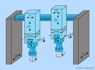
On machine tools with separately movable heads on which a transformation must be activated, the orientation axes cannot be coupled using the standard coupling methods (COUPON, TRAILON).
The axes participating in the coupling are determined via axial machine data that is updated with RESET. This makes it possible to redefine pairs of axes during operation and enable and disable them via CNC language commands.
There are master and slave axes. A master axis can have more than one slave axis, but a slave axis cannot be a master axis at the same time (no cascading). To protect the heads from collisions, collision protection can be set and activated either via machine data or the VDI interface.
Axis data output via PROFIBUS ADAS (option N07)
The loadable compile cycle supports output of axis and spindle data to a special PROFIBUS slave module.
This function can be used, for example, for process or machine monitoring functions in real time outside the CNC. The required axis and signal type are selected by transferring a selection command (length: 8 bytes) to the CNC.
The compile cycle in the NC kernel then sends up to 30 axis data items (of 4 bytes each) to the slave in each PROFIBUS cycle. With the slaves in isochronous mode, the transfer cycle can be equal to the position control cycle, or a multiple of it.
Axis limitation from the PLC
> Protection areas
The preactivation of protection zones with specification of a position offset is programmed in the part program. You can put the preactivated protection zones into effect in the PLC user program via the PLC interface. As a result, the relevant protection zone is activated, for example, before a tool probe is swiveled into position in the working area, to see whether the tool or a workpiece is in the path of the swiveling part.
The PLC can put another axis limitation into effect by activating the 2nd software limit switch via a PLC interface signal. This reduction of the working area may become necessary, for example, when a tailstock is swiveled into position. The change is immediately effective, and the 1st software limit switch plus/minus is no longer valid.
Axis/spindle replacement
An axis/a spindle is permanently assigned to a specific channel via machine data. The axis/spindle replacement function can be used to release an axis/a spindle (RELEASE) and to assign it to another channel (GET), i.e., to replace the axis/spindle. The relevant axes/spindles are determined via machine data.
Backlash compensation
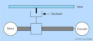
Positive backlash (normal case)
The actual encoder value is ahead of the true actual value (table): The table does not travel far enough.
During power transmission between a moving machine part and its drive (e.g., ball screw), there is normally a small amount of backlash because setting mechanical parts so that they are completely free of backlash would result in too much wear and tear on the machine. In the case of axes/spindles with indirect measuring systems, mechanical backlash results in corruption of the traverse path. For example, when the direction of movement is reversed, an axis will travel too much or too little by the amount of the backlash.
To compensate for backlash, the axis-specific actual value is corrected by the amount of the backlash every time the axis/spindle reverses its direction of movement.
If a 2nd measuring system is available, the relevant backlash on reversal must be entered for each of the two measuring systems. Backlash compensation is always active in all modes following reference point approach.
Block search
The block search function allows any point in the part program to be selected, at which machining must start or be continued. The function is provided for the purpose of testing part programs or continuing machining after a program abort. Cascaded block search is also possible.
You have a choice of 4 different search options:
- Block search with calculation at the contour:
During the block search, the same calculations are executed as during normal program operation. The target block is then traversed true-to-contour until the end position is reached. Using this function it is possible to approach the contour again from any situation. - Block search with calculation at the block end point:
This function allows you to approach a target position (such as tool change position). All calculations are also executed here as during normal program operation. The end point of the target block or the next programmed position is approached using the method of interpolation valid in the target block. - Block search without calculation:
This method is used for high-speed searches in the main program. No calculations are carried out during the search. The internal control values remain the same as before the block search. - External block search without calculation:
In the menus "Search position" and "Search pointer", you can use the softkey "External without calc." to start an accelerated block search for programs which are executed by an external device (local hard disk or network drive).
You can specify the search destination by:
- Directly positioning the cursor on the target block
- Specifying a block number, a jump label, any character string, a program name, or a line number
Cartesian PTP travel
For handling and robot-related tasks, two types of movement are required, either in the Cartesian coordinate system (continuous path, CP), or as a point-to-point (PTP) movement. With PTP, the shortest way to reach the end point is with activated (!) TRAORI transformation. PTP generates a linear interpolation in the axis space of the machine axes. By smoothing from PTP to CP movement, it is possible to switch from fast infeed to a mounting or positioning movement with optimum timing.
PTP travel does not result in an axis overload when traveling through a singularity, such as the changing of an arm position during handling.
PTP travel is also possible in JOG mode and does not require Cartesian positions (e.g., from CAD systems) to be converted into machine axis values. Cartesian PTP travel is also used for cylindrical grinding machines with an inclined axis: With active transformation, the infeed axis can be moved either according to Cartesian coordinates or at the angle of the inclined axis.
Circle via center point and end point
Circular interpolation causes the tool to move along a circular path in a clockwise or counter-clockwise direction. The required circle is described by:
- Starting point of circular path (actual position in the block before the circle)
- Direction of rotation of circle
- Circle end position (target defined in circular block)
- Circle center
The circle center can be programmed as an absolute value with reference to the current zero point or as an incremental value with reference to the starting point of the circular path.
If the opening angle is apparent from the drawing, then it can be directly programmed.
In many cases, the dimensioning of a drawing is chosen so that it is more convenient to program the radius in order to define the circular path. In the case of a circular arc of more than 180 degrees, the radius specification is given a negative sign.
Circle via intermediate point and end point
If a circle is to be programmed, which does not lie in a paraxial plane but obliquely in space, an intermediate point can be used to program it instead of the circle center. Three points are required to program the circle: the starting point, intermediate point and end point.
Clamping monitoring
> Position monitoring, standstill monitoring
Clamping monitoring is one of SINUMERIK's many extensive monitoring mechanisms for axes.
When an axis is to be clamped on completion of the positioning action, you can activate clamping monitoring using the PLC interface signal "clamping in progress". This may become necessary because it is possible for the axis to be pushed beyond the standstill tolerance from the position setpoint during the clamping procedure. The amount of deviation from the position setpoint is set via the machine data. During the clamping procedure, clamping monitoring replaces standstill monitoring, and is effective for linear axes, rotary axes, and position-controlled spindles. Clamping monitoring is not active in follow-up mode. When the monitor responds, its reactions are the same as those of the standstill monitor.
Clearance control 1D in the IPO cycle
Clearance control 1D in the IPO cycle can be used, for example, to evaluate sensor signals via a high-speed analog input. It can also be used to compute a position offset $AA_OFF for an axis via a synchronous action.
Clearance control 1D/3D in the position-control cycle (option M40)
Clearance control 1D/3D in the position-control cycle (which includes the IPO cycle) controls three machine axes as well as a gantry axis and makes it possible to automatically maintain the constant clearance that is technologically required for the machining process.
The most important applications for this are water jet cutting and laser cutting, for example, the radial cutting of rods with non-circular cross sections.
Limited functionality of export control versions:
Clearance control 1D in the position-control cycle only, number of interpolating axes restricted to 4.
CNC program messages
> Alarms and messages
All messages programmed in the part program and all alarms recognized by the system are displayed on the operator panel in plain text. Alarms and messages are displayed separately. You can program messages in order to provide the operator with the latest information on the current machining situation during the program run.
CNC user memory
All programs and data, such as part programs, subprograms, comments, tool offsets, and work offsets/frames, as well as channel and program user data, can be stored in the shared CNC user memory. The CNC user memory is battery-backed.
Compensation of a forced mechanical coupling, AXCO (option)
The loadable compile cycle allows a movement of an axis that occurs due to mechanical coupling of an axis to a following axis, to be compensated such that the axis remains mechanically stationary despite the coupling. The motor of the coupled axis, in this case, is rotated in the set coupling ratio.
Concatenated transformations
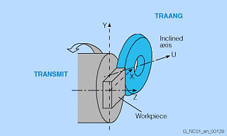
Grinding a TRANSMIT contour with inclined axis
With the TRACON command, two transformations can be concatenated: TRAANG (inclined axis), as the base transformation, can be linked with TRAORI (5-axis transformation), TRANSMIT (front end machining of turned parts) or TRACYL (cylinder surface transformation).
Applications:
- Rotary milling with mechanically non-orthogonal Y axis to X, Z (inclined-bed rotary milling machine)
- Grinding of contours programmed with TRACYL (cylinder processing)
- Finishing of a distorted contour created with TRANSMIT
Continue machining at the contour (Retrace Support) (option M24)
When using 2D flat bed cutting procedures, e.g., laser, oxygen or water jet cutting, the machine operator can return to the program continuation point (selected solely for the view of the workpiece) following an interruption in machining without exact knowledge of the part program in order to continue machining the workpiece from there.
The Continue machining at the countour function (Retrace Support) contains a ring buffer for the geometric information of the blocks already executed.
A new part program is generated from this for the reverse travel. Retracing is used, for example, when the machine operator only notices the failure or interruption a few blocks after the actual interruption. The head has usually already progressed further in the machining, and must, therefore, be appropriately returned for continuation of machining.
Continuous dressing (parallel dressing)
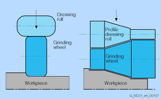
Parallel dressing
With this function, the form of the grinding wheel can be dressed in parallel with the machining process. The grinding wheel compensation resulting from dressing the wheel takes immediate effect as tool length compensation.
When the tool radius compensation is programmed to machine the contour and the tool radius changes because of the dressing of the grinding wheel, the CNC computes the dressing amount online as a true tool radius compensation.
Continuous-path mode with programmable rounding clearance
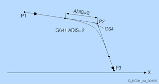
Continuous-path mode with programmable rounding clearance
The aim of the continuous-path mode is to avoid excessive deceleration at the block boundaries and to achieve as constant a tool path velocity as possible during tangential transitions from one block to the next. Because the tool does not stop at block boundaries, no undercuts are made on the workpiece. If continuous-path mode (G64) is selected, reduction in velocity takes place and contour corners are rounded on non-tangential transitions. A soft contour transition without a jump in acceleration can be programmed with G641 ADIS=...
Contour definition programming
Contour definition programming allows you to input simple contours quickly. With the aid of help displays in the editor, you can program 1-point, 2-point or 3-point definitions with transition elements chamfer or corner easily and clearly by entering Cartesian coordinates and/or angles.
Contour handwheel (option M08)
> Feedrate interpolation
When the contour handwheel function is activated, the handwheel has a velocity-generating effect in AUTOMATIC and MDI modes on all programmed traversing movements of the path and synchronized axes.
A feedrate specified via the CNC program becomes ineffective and a programmed velocity profile is no longer valid. The feedrate, in mm/min, results from the handwheel pulses as based on pulse weighting (machine data) and the active increment. The handwheel's direction of rotation determines the direction of travel:
- Clockwise:
In the programmed direction of travel (even beyond block boundaries) - Counter-clockwise:
Against the programmed direction of travel (continuation beyond the start of the block is prevented)
Contour monitoring
> Travel to fixed stop
The following error is monitored within a definable tolerance band as a measure of contour accuracy. An impermissibly high following error might be caused by a drive overload, for example. If an error occurs, the axes/spindles are stopped.
"Contour monitoring" is always enabled when a channel is active and in position-controlled mode.
If the channel is interrupted or in the reset state, contour monitoring is not active. Contour monitoring is also deactivated during execution of the "travel to fixed stop" function.
Contour monitoring with tunnel function (option M52)
With the "contour monitoring with tunnel function" function, the absolute movement of the tool tip in space can be monitored in 5-axis machining or when complex workpieces are being machined. This function provides optimum protection for high-quality workpieces. A cylindrical tunnel (tolerance field) with a definable diameter is placed around the programmed path.
If during machining the deviation from the path caused by axis errors is greater than the defined tunnel diameter, the axes are brought to a standstill immediately. The deviation from the path can be written simultaneously to an analog output.
Control unit management
The Thin Client Unit (TCU) for distributed installation allows the spatial separation of SINUMERIK OP (TP) operator panel fronts and SINUMERIK PCUs, as well as the connection of up to 4 operator panel fronts to a PCU with one TCU each. To this end, the user interface of a PCU 50.3 is copied to several OPs with one TCU each. Advantages:
- Low-vibration installation of the PCU in the control cabinet
- Efficient operation of larger machines using up to 5 uniform operator panels
- Signal transmission between PCU and operator panel front via Industrial Ethernet
- Operation on the active operator panel with the option to enable the passive operator panel on request
- Mixed operation of operator panel fronts on a TCU or with an integrated TCU and an operator panel front directly connected to the PCU possible
- Distance between PCU and operator panel fronts of up to 100 m (max. distance between two network nodes)
Crank interpolation "CRIP" (option)
It supports simple programming and machining of pin bearing seats on a crankshaft. The function can be utilized in more than one channel, which means that a single workpiece can be machined simultaneously with several grinding units. The function calculates the compensating movement of the grinding wheel in relation to the rotating workpiece surface. As with normal cylindrical grinding, the pin bearing journal is programmed as a radial distance X between the workpiece and grinding wheel.
Cross-mode actions (option M43)
> Interrupt routines with fast retraction from the contour
Asynchronous subprograms (ASUB) make it possible to respond immediately to high-priority events not only during program execution, but in all modes and program states.
In the case of such an interrupt, it is also possible to start an asynchronous subprogram in manual modes. The asynchronous subprogram can be used, for example, to bring the grinding wheel to a safe position to avoid collision. This option also enables statically effective IDS synchronous actions, which are active in all modes.
Cycle protection (OEM) (option P54)
With cycle protection, cycles can be encrypted and then stored protected in the control. Execution in the NC is possible without restrictions, but it is not possible to view the cycle. This protects the internal company know-how. The cycle can, however, be copied in encrypted form. It can, therefore, be used on other machines.
If this should also be prevented, the cycle can be permanently bound to a particular CNC hardware unit by means of an addition to the program.
Cycle support
> SINUMERIK Operate runtime license OA Easy Screen
The technology cycles for drilling, milling and turning and the measuring cycles are supported by cycle screens. Similar input displays are also available for geometric contour programming. You can, however, also define a number of softkeys, input fields and displays yourself using the "Expand user interface" or "Easy Screen" function.
Data exchange between machining channels
> High-level CNC language
In the "program coordination" function, variables shared by the channels (NCK-specific global variables) can be used for data exchange between the programs. The program message itself is separate for each channel.
Diagnostics functions
For service purposes, a self-diagnostics program and testing aids have been integrated in the controls. The status of the following can be displayed on the operator panel:
- Interface signals between the CNC and the PLC and between the PLC and the machine
- Data blocks
- PLC bit memories, timers and counters
- PLC inputs and outputs
For testing purposes, signal combinations can be set for the output signals, input signals, and bit memories. All alarms and messages are displayed in plain text on the operator panel along with the corresponding acknowledgement criterion. Alarms and messages are displayed separately.
In the "service display" menu, it is possible to call up important information about the axis and spindle drives, such as:
- Absolute actual position
- Position setpoint
- Following error
- Speed setpoint
- Actual speed value
- Trace of CNC and drive variables
Dimensions metric/inches
Depending on the measuring system used in the production drawing, you can program workpiece-related geometrical data in either metric measure (G71) or inches (G70). The control can be set to a basic system regardless of the programmed dimensional notation. You can enter the following geometrical data directly and let the control convert them into the other measuring system (examples):
- Position data X, Y, Z, etc.
- Interpolation parameters I, J, K and circle radius CR
- Pitch
- Programmable work offset (TRANS)
- Polar radius RP
With the G700/G710 programming expansion, all feedrates are also interpreted in the programmed measuring system (inch/min or mm/min). In the "Machine" operating area, you can switch back and forth between inch and metric dimensional notation using a softkey.
Display functions
All current information can be displayed on the operator panel's screen, such as:
- Block currently being executed
- Previous and following block
- Actual position, distance-to-go
- Current feedrate
- Spindle speed
- G functions
- Auxiliary functions
- Workpiece designation
- Main program name
- Subprogram name
- All data entered, such as part programs, user data and machine data
- Help texts
Important operating states are displayed in plain text, for example:
- Alarms and messages
- Position not yet reached
- Feed stop
- Program in progress
- Data input/output in progress
DOUBLETRANSMIT transformation, 2TRA (option M25)
The function supports machining on the end face or peripheral surface with a driven tool that is always held vertically with respect to the contour by means of an appropriate swivel movement and balancing movement in X.
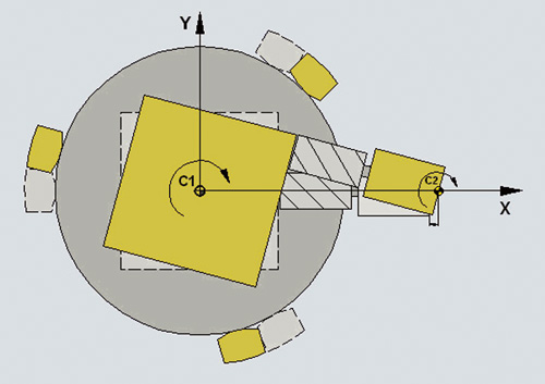
Transformation, doubletransmit
DRF offset (differential resolver function)
> Handwheel override
The differential resolver function generates an additional incremental work offset in AUTOMATIC mode via the electronic handwheel. This function can be used, for example, to correct tool wear within a programmed block.
Dynamic preprocessing memory (FIFO)
The traversing blocks are readied prior to execution and stored in a preprocessing memory (FIFO = first in/first out) of specifiable size. In contour sections that are machined at high velocity with short path lengths, blocks can be executed from this preprocessing memory at very high speed. The preprocessing memory is constantly reloaded during execution.
Block execution can be interrupted with the STARTFIFO command until the preprocessing memory been filled, or STOPFIFO (start high-speed machining section) or STOPRE (stop preprocessor) can be programmed.
Easy Screen (option P64)
> SINUMERIK Operate runtime license OA Easy Screen
Electronic gear (option M22)
The electronic gear function allows highly accurate kinematic coupling of axes with programmable gear ratio. Linking can be specified and selected for any CNC axes via program or operator panel.
The electronic gear function makes it possible to control the movement of a following axis, depending on up to 5 master axes.
The relations between the master axis and the following axis are defined for each master axis by a fixed gear ratio (numerator/denominator) or as a linear or non-linear coupling using a curve table. The following axis can be a master axis for another gear system (cascading). Real as well as simulated linear and rotary axes can be used as the master and following axes. Master input values can be setpoints generated by the interpolator (setpoint linkage) or actual values delivered by the measuring system (actual-value linkage). Using the electronic gear with non-linear coupling, it is possible to create convex tooth faces during gear cutting and also to compensate the non-linear properties of the process, for example.
Limited functionality of export control versions: The number of simultaneously traversing axes is restricted to 4.
Electronic handwheels
Using electronic handwheels, it is possible to move selected axes simultaneously in manual mode. The handwheel clicks are analyzed by the increment analyzer. If coordinate offset or coordinate rotation is selected, it is also possible to move the axes manually in the transformed workpiece coordinate system. The maximum input frequency of the handwheel inputs is 100 kHz.
A third handwheel can also be operated as a contour handwheel.
The "contour handwheel" function permits use of a handwheel on conventional turning machines (for ShopTurn applications, for example) and also during grinding for traversing on a contour.
Once the "contour handwheel" function has been activated, the handwheel has a velocity-generating effect in AUTOMATIC and MDA modes, i.e., a feedrate specified via the CNC program is no longer effective and a programmed velocity profile is no longer valid. The feedrate, in mm/min, results from the handwheel pulses as based on pulse evaluation (via machine data) and the active increment (INC1, INC10, etc.).
The handwheel's direction of rotation determines the direction of travel: clockwise in the programmed direction, even over block boundaries, and counter-clockwise up to the block start.
Electronic transfer (option M35)
> Position switching signals/cam controller
> Polynomial interpolation
> Master value coupling and curve table interpolation
> Cross-mode actions
> I/O interfacing via PROFIBUS DP
> Synchronized actions stage 2
> Pairs of synchronized axes (gantry axes)
In presses with transfer step tools as well as in large-part transfer presses, a modern transfer system handles part transport. Positioning drives are controlled in step with the press's main motions. The "electronic transfer" option makes it possible to control sequences of motion in transfer systems (such as gripper or suction lines, etc.), depending on a master value, which corresponds to the current ram position of the press. The "electronic transfer" option contains secondary options for "position switching signals/cam controller", "polynomial interpolation", "master value coupling and curve table interpolation", "cross-mode actions", "I/O interfacing via PROFIBUS DP", "synchronized actions stage 2", as well as two "pairs of synchronized axes (gantry axes)". Combinations of these individual options satisfy all requirements for highly dynamic and accurate transfer controls. When using the "electronic transfer" option, the "spindle" and "tool offset" functions cannot be activated.
Limited functionality of export control versions: The number of simultaneously traversing axes is restricted to four.
Electronic transfer CP (option M76)
> Position switching signals/cam controller, > Polynomial interpolation, > Generic couplings,
> Cross-mode actions, > I/O interfacing via PROFIBUS DP, > Synchronized actions stage 2,
> Pair of synchronized axes (gantry axes)
In presses with transfer step tools as well as in large-part transfer presses, a modern transfer system handles part transport. Positioning drives are controlled in step with the press's main motions. The "Electronic transfer CP" option makes it possible to control sequences of motion in transfer systems (such as gripper or suction lines, etc.), depending on a master value, which corresponds to the current ram position of the press. The "Electronic transfer CP" option includes the options:
- Position switching signals/cam controller
- Polynomial interpolation
- Generic coupling CP Comfort
- Cross-mode actions
- I/O interfacing via PROFIBUS DP
- Synchronized actions stage 2
- Pairs of synchronized axes (gantry axes)
Combinations of these individual options satisfy all requirements for highly dynamic and accurate transfer controls. When using the "Electronic transfer CP" option, the "Spindle" and "Tool offset" functions cannot be activated.
Limited functionality of export control versions: The number of simultaneously traversing axes is restricted to 4.
Electronic weight counterbalance
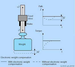
Electronic weight counterbalance
With weight-loaded axes without mechanical or hydraulic weight counterbalance, the vertical axis drops when the brake is released and the servo enable is switched on. The undesired lowering (dZ) of the axis can be compensated by activating electronic weight counterbalance. After releasing the brake, the constant weight counterbalance torque maintains the position of the vertical axis.
Sequence:
1. Brake holds Z axis.
2. Brake is released; servo enable on; pulse enable on
3. Z axis does not drop, holding its position.
Evaluation of internal drive variables (option M41)
The evaluation of internal drive variables can be used to control (adaptive control) a second process variable (such as a path-specific or axis-specific feedrate) depending on a measured process variable (such as spindle current).
This permits, for example, the cutting volume to be kept constant when grinding, or faster covering of the grinding gap when scratching (first touch). Evaluation of these drive variables also permits machines and tools to be protected from overloading, as well as shorter machining times and an improved surface quality for the workpieces to be achieved.
Evaluation of internal drive variables is a prerequisite for implementing adaptive control (AC). Adaptive control can be parameterized within the part program as follows:
- Additive influence: The programmed value (F word) is corrected by adding.
- Multiplicative influence: The F word is multiplied by a factor (override).
The following real-time variables can be evaluated as internal drive variables:
$AA_LOAD drive capacity utilization in %
$AA_POWER drive active power in W
$AA_TORQUE drive torque setpoint in Nm
$AA_CURR actual axis/spindle current in A
Extended stop and retract (incl. generator operation) (option M60)
A safe position is assumed from the machining level without any collision between tool and workpiece.
As well as the drive-autonomous stop and retract function, the "CNC-controlled stop and retract" functionality is also provided. To permit gentle interpolated retraction on the path or contour, the path interpolation can be processed further for a definable period following the triggering event. The retraction axes are subsequently traversed in synchronism to an absolute or incremental position as programmed.
These functions are primarily used for gearing and grinding technologies.
Fast-IPO-Link (option M12)
Non-circular machining can be carried out for general workpiece contours using polynomial interpolation or, with sinusoidal default settings, using master value coupling and curve table interpolation.
In the case of very fast non-circular machining, Fast-IPO-Link permits transfer of the non-circular task (e.g. movement of X axis) to a separate NCU with fast cycle. Speeds greater than 3,000 rpm can then be achieved for sinusoidal movements.
Feedforward control
The following errors can be reduced to almost zero with feedforward control. This feedforward control is therefore also called following error compensation. Particularly during acceleration in contour curvatures, e.g. circles and corners, this following error leads to undesirable, velocity-dependent contour violations.
- Velocity-dependent speed feedforward control (basic version):
In velocity-dependent feedforward control, the following error can be reduced almost to zero at constant velocity. - Acceleration-dependent torque feedforward control (option):
In order to achieve precise contours even when the demand for dynamics is at its highest, you can use torque feedforward control. If the settings are right, you can compensate the following error almost completely, even during acceleration. The result is excellent machining precision even at high tool path feedrates.
Feedrate interpolation (feed characteristic)
> Polynomial interpolation
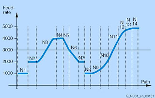
Programming example for feedrate interpolation
N1 Constant feedrate profile F1000: FNORM
N2 Abrupt set velocity change F2000: FNORM
N3 Feedrate profile via polynomial : F = FPO (4000, 6000, -4000)
N4 Polynomial feedrate 4000 as modal value
N5 Linear feedrate profile F3000: FLIN
N6 Linear feedrate 2000 as modal value
N7 Linear feedrate, as modal value
N8 Constant feedrate profile with abrupt acceleration change F1000: FNORM
N9 All subsequent F values are linked by splines F1400: FCUB
N13 Switch off spline profile
N14 FNORM
In accordance with DIN 66025, a constant feedrate over the part program block can be defined via address F. For a more flexible definition of the feedrate profile, programming to DIN 66025 is extended by linear and cubic profiles over the path. The cubic profiles can be programmed directly or as an interpolating spline.
This makes it possible, depending on the curvature of the workpiece to be machined, to program continually smooth velocity profiles, which in turn allow jerk-free acceleration changes and thus the production of uniform workpiece surfaces. You can program the following feedrate profiles:
- FNORM
Behavior as per DIN 66025 (default setting). An F value programmed in the CNC block is applied over the entire path of the block, and is subsequently regarded as a fixed modal value. - FLIN
An F value programmed in the block can be traversed linearly (rising or falling) over the path from the current value at the beginning of the block to the end of the block, and is subsequently regarded as modal value. - FCUB
The non-modally programmed F values, referred to the end of the block, are connected through a spline. The spline starts and ends tangentially to the previous or following feedrate setting. - FPO
You can also program the feedrate profile directly via a polynomial. The polynomial coefficients are specified analogous to polynomial interpolation.
Feedrate override
The programmed velocity is overridden by the current velocity setting via the machine control panel or by the PLC (0 % to 200 %). In order for the cutting velocity on the contour to be kept constant, the feedrate calculation is referred to the operating point or tool end point. The feedrate can also be corrected by a programmable percentage factor (1 % to 200 %) in the machining program. This factor is overlaid (multiplication) on the setting made on the machine control panel. The velocity setting from the PLC is axis-specific.
Follow-up mode
In follow-up mode, an axis/a spindle can be moved independently, while the actual value continues to be detected. The traverse paths are updated in the display. Standstill, clamping and positioning monitoring functions are not effective in follow-up mode. Once follow-up mode is cancelled, reference-point approach of the axis does not have to be repeated.
Frame concept
Frame is the common term for a geometric expression describing an arithmetic operation, for example, translation or rotation.
On SINUMERIK controls, the frame in the CNC program transfers from one Cartesian coordinate system to another, and represents the spatial description of the workpiece coordinate system.
The following are possible:
- Basic frames: Coordinate transformation from basic coordinate system (BCS) into basic zero system (BZS)
- Settable frames: Work offsets using G54 to G57/G505 to G599
- Programmable frames: Definition of workpiece coordinate system (WCS)
The frame concept makes it possible to transform Cartesian coordinate systems very simply by offsetting, rotating, scaling and mirroring.
The following instructions are used to program these options:
- TRANS programmable work offset
- ROT rotation in space or in a plane
- ROTS rotation referred to the solid angle projected into the planes
- SCALE scaling (scale factor)
- MIRROR mirroring
- TOFRAME frame according to tool orientation
- TOROT rotary component of programmed frame
- PAROT frame for workpiece rotation (table rotation)
- MEAFRAME frame calculation from three measuring points in space (for measuring cycles)
The instructions can also be used several times within one program. Existing offsets can either be overwritten or new ones can be added.
Additive frame instructions:
ATRANS additive programmable work offset
AROT additive rotation in space or in a plane
ASCALE scale factor (multiplication)
AMIRROR repeated mirroring
AROTS additive rotation referred to the solid angle projected into the planes
If swivel-mounted tools or workpieces are available, machining can be implemented very flexibly, for example:
- By machining several sides of a workpiece by rotation and swiveling of the machining plane
- By machining of inclined surfaces using tool length and tool radius compensation
Generator operation
With the generator operation function, brief power outages can be bridged or power provided for retraction. To make this possible, the energy stored during spindle rotation or axis movement is fed back into the DC link, following the same principle as that used by generators.
Generic coupling Basic: CP Basic (option M72)
This option offers:
- Up to 4 x coupled motion and
- 1 x Synchronous spindles/multi-edge turning or Master value coupling/curve table interpolation or Axial coupling in the machine coordinate system
Generic coupling Comfort: CP Comfort (option M73)
This option offers:
> Up to 4 x coupled motion and
> Up to 4 x Synchronous spindles/multi-edge turning and/or Master value coupling/curve table interpolation and/or Axial coupling in the machine coordinate system
Also
> 1 x Electronic gear unit function for up to 3 master axes is possible (without curve table interpolation and without cascading).
Generic coupling Expert: CP Expert (option M74)
This option offers:
- Up to 8 x coupled motion and
- Up to 8 x Synchronous spindles/multi-edge turning and/or Master value coupling/curve table interpolation and/or Axial coupling in the machine coordinate system
Also:
- Up to 8 x Electronic gear unit function for up to 3 master axes as well as
- Up to 5 x Electronic gear unit function for up to 5 master axes (each with curve table interpolation and with cascading).
The CP Expert option is only possible in combination with NCU 720/730.
Generic coupling Standard: CP Standard
The basic version already offers:
- Up to 4 x simple coupled motion (with one master axis, not used with synchronized actions)
Generic coupling Static: CP Static (option M75)
This option offers:
- One simple synchronous spindle (with coupling ratio 1:1, no multi-edge machining)
Generic couplings (basic version/options)
For generic (general) coupling (CP) of axes/spindles, we offer 5 different performance levels. The functionality is scalable via the number of master axes to one slave axis, via coupling characteristics ranging from simple functionality through to technological innovations and via the simultaneously activatable coupling types. The options CP Static, CP Basic, CP Comfort and CP Expert are available. These options can be combined as required.
Functionality limitations on the SINUMERIK 840DE sl/840DiE sl: see the functional limitations for each of the above-mentioned functions and options.
Geometry axes, switchable online in the CNC program
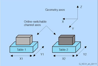
Geometry axes, switchable online
In the CNC, geometry axes form axis groupings per channel for the interpolation of path motions in space.
Channel axes are assigned to geometry axes via machine data.
With the switchable geometry axes function, it is possible, from the part program, to assemble the geometry axis grouping from other channel axes. This makes problem-free operation of machine kinematics with parallel axes possible.
Grinding wheel surface speed, constant
Automatic conversion of the grinding wheel surface speed to a speed of rotation as a function of the current grinding wheel diameter. This function can be active for several grinding wheels simultaneously in one CNC channel. The grinding wheel surface speed is monitored.
A constant grinding wheel surface speed is not only useful during processing of a part program in AUTOMATIC and MDA modes, but can also be effective immediately after power-up of the control, on reset, and at the end of the part program, and remain in force beyond all mode changes (depending on the machine data).
Handling package (option S31)
For handling systems, the handling package offers a cost-effective solution:
- 3 additional axes
- 3 additional channels
- Transformation package Handling (option M31; requires a loadable compile cycle)
- Synchronized actions stage 2 (option M36)
- No tool offsets and no spindles
Handwheel override
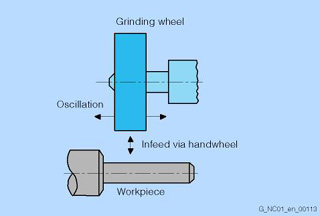
Handwheel override in AUTOMATIC mode
With the handwheel override function, an axis can be traversed or the velocity of an axis can be overridden. The function is effective blockwise.
At the same time, additional axes can be traversed simultaneously or using interpolation. The actual-value display is continuously updated.
Application: Grinding machines
Helical interpolation 2D+6
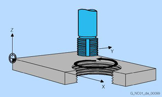
Helical interpolation: Thread milling with form cutter
The helical interpolation function is ideal for machining internal and external threads using form milling cutters and for milling lubrication grooves. The helix comprises two movements:
- Circular movement in one plane
- Linear movement perpendicular to this plane
The programmed feedrate F either refers only to the circular movement or to the total path velocity of the three CNC axes involved.
In addition to the two CNC axes performing circular interpolation, other linear movements can be performed synchronously. The programmed feedrate F refers to the axes specially selected in the program.
Limited functionality of export control versions: Not possible.
High-level CNC language
To meet the various technological demands of modern machine tools, a CNC high-level language has been implemented in SINUMERIK that provides a high degree of programming freedom.
System variables
The system variables ($.) can be processed in the CNC program (read, partially write). System variables allow access to, for example, machine data, setting data, tool management data, programmed values, and current values.
User variables
If a program is to be used flexibly, variables and parameters are used instead of constant values.
SINUMERIK gives you the option of executing all CNC functions and addresses as variables. The names of the variables can be freely defined by the user. Read and write access protection can also be assigned using attributes. This means that part programs can be written in a clear and neutral fashion and then adapted to the machine as required, for example, free selection of axis and spindle address designations.
User variables are either global (GUD) or local (LUD). LUD can also be redefined via machine data to make them into global program user variables (PUD). They are displayed in the Parameters operating area under the user data softkey, where they can also be changed.
Global user variables (GUD) are CNC variables that are set up by the machine manufacturer. They apply in all programs.
Local user data (LUD) are provided for parameterizing CNC programs. These data can be redefined in every CNC program. These variables make programming more user-friendly and allow the users to integrate their own programming philosophy.
Indirect programming
Another option for the universal use of a program is indirect programming. Here, the addresses of axes, spindles, R parameters, etc., are not programmed directly, but are addressed via a variable in which their required address is then entered.
Program jumps
The inclusion of program jumps allows extremely flexible control of the machining process. Conditional and unconditional jumps are available as well as program branches that depend on a current value. Labels that are written at the beginning of the block are used as jump destinations. The jump destination can be before or after the exit jump block.
Program coordination (in several channels)
Program coordination makes it possible to control the time-related execution in parallel operation of several CNC channels using plain text instructions in the part program. Programs can be loaded, started and stopped in several channels. Channels can be synchronized.
Arithmetic and trigonometric functions
Extensive arithmetic functions can be implemented with user variables and arithmetic variables. In addition to the 4 basic arithmetic operations, there are also:
- Sine, cosine, tangent
- Arc sine, arc cosine, arc tangent
- Square root
- Absolute value
- Power of 2 (squaring)
- Integer component
- Round to integer
- Natural logarithm
- Exponential function
- Offset
- Rotation
- Scale modification
- Mirroring
Comparison operations and logic combinations
Comparison operations with variables can be used to formulate jump conditions. The comparison functions that can be used are:
- Equal to, not equal to
- Greater than, less than
- Greater than or equal to
- Less than or equal to
- Concatenation of strings
The following logic combinations are also available: AND, OR, NOT, EXOR
These logic operations can also be performed bit by bit.
Macro techniques
Using macros, single instructions from a programming language can be grouped together to form a complex instruction. This shortened instruction sequence is given a freely definable name and can be called in the CNC program. The macro command is executed in the same way as the single instructions.
Control structures
The control normally processes the CNC blocks in the order in which they are programmed.
Like program jumps, control structures allow the programmer to define additional alternatives and program loops. The commands make structured programming possible, and make the programs much easier to read:
- Choice of 2 alternatives (IF-ELSE-ENDIF)
- Continuous loop control (LOOP)
- Counting loop (FOR)
- Program loop with start condition (WHILE)
- Program loop with end condition (REPEAT)
High-speed CNC inputs/outputs
> Position switching signals/cam controller
The "high-speed CNC inputs/outputs" function supports the input or output of signals in the position-control/interpolation cycle.
The high-speed CNC inputs/outputs can be used for machines, such as those used for grinding and laser machining, as well as in SINUMERIK Safety Integrated.
Input signals are possible for the following:
- Multiple feedrate values per block (calipers function)
The function allows modification of the feedrate through external signals. Six digital inputs can be combined with six different feedrate values in a CNC block. There is no feed interruption in this case. An additional input can be used for infeed termination (starting a dwell time), and another input can be used to start an immediate retraction movement. Depending on the input, the retraction of the infeed axis (or axes) is initiated by a previously specified absolute value in the IPO cycle. The remaining residual distance is deleted. - Multiple auxiliary functions in the block
Several auxiliary functions can be programmed in one CNC block. These functions are transferred to the PLC depending on a comparison operation or on an external signal. - Axis-specific deletion of the residual distance
The high-speed inputs affect a conditional stop and delete the residual distance for the path or positioning axes. - Program branches
The high-speed inputs make program branches within a user program possible. - Fast CNC start
Machining can be enabled conditionally in the CNC program depending on an external input. - Analog calipers
Various feedrates, a dwell time and a retraction path can be activated depending on an external analog input (threshold values are specified via machine data). - Safety-related signals such as EMERGENCY STOP
Output signals are possible for the following:
- Position switching signals
The position switching signals can be output with the function “Position switching signals/cam controller”. - Programmable outputs
- Analog-value output
- Safety-related signals such as safety door interlock
HMI programming package sl/HMI runtime license OA programming (option P60)
> SINUMERIK Operate programming package / SINUMERIK Operate runtime license programming
"IMD base" (option)
This option supports the "Tool missing" monitoring function as well as programming the maximum permissible overload for a tool.
The parameters are taught on program setup as for the "Missing tool" monitoring function, and saved in the function-specific global user data (GUD). For all subsequent program runs, the taught signals will be compared with the current ones and tool overload is avoided.
Language command in the part program: CC_START_TASK("Fixed_Overload", …, ...)
The compile cycle "IMD base" is also the prerequisite (interface) for customized add-ons in the field of process monitoring and diagnostics. The openness in the real-time part of the SINUMERIK 840D sl is utilized, for example, by the SINUMERIK Solution Partners.
"IMD light" (option)
This option supports a "Tool missing" monitoring function within the IMD package. For this purpose, cuts (transition from rapid traverse to creep feed) must be selected and parameterized (CC_START_TASK( "MissingTool", …, ...) in the part program. For example, select "Torque of spindle" or "Torque of a specific axis". The torque can be learned in an initial program run (teach-in). In productive operation, the tool is assumed to be present when the actual signal is equal to the taught signal. If not, an individually parameterized alarm response is triggered (RESET, CANCEL, Stop Spindle, Stop Axes, etc.).
I/O interfacing via PROFIBUS DP
PROFIBUS DP represents the protocol profile for distributed I/Os. It enables high-speed cyclic communication. Advantages of PROFIBUS DP: very short bus cycle times, high degree of availability, data integrity, and standard message frame structure.
Inclined axis (option M28)
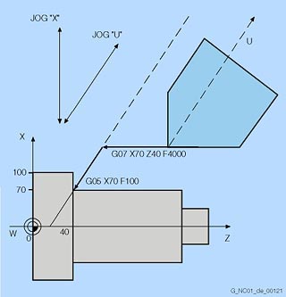
Oblique plunge-cut grinding: machine with non-Cartesian X axis (U)
The "Inclined axis" function is used for fixed-angle interpolation using an oblique infeed axis (used primarily in conjunction with cylindrical grinding machines). The axes are programmed and displayed in the Cartesian coordinate system.
Tool offsets and work offsets are also entered in the Cartesian system and transformed to the real machine axes.
For oblique plunge-cutting with G05, it is necessary to program the start position with G07. In JOG mode, the grinding wheel can be traversed either in the Cartesian coordinate system or in the direction of inclined axis U (selection via the channel DB).
Inclined-surface machining with frames
> Frame concept
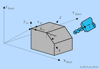
Inclined-surface machining with frames
Drilling and milling operations on workpiece surfaces that do not lie in the coordinate planes of the machine can be performed easily with the aid of inclined-surface machining. The position of the inclined surface in space can be defined by coordinate system rotation.
Integrated tool monitoring and diagnostics "IMD"
The compile cycle "Integrated Monitoring & Diagnostics" is a software package with easy access to drive data (drive torque, encoder values, setpoint speed, etc.) and program data (programmed distance, programmed speed, programmed interpolation type, etc.) directly in the real-time part of the control. The function offers interfaces to the part program (language commands), to the PLC (fast I/O) and to the HMI (files, GUD).
Intermediate blocks for tool radius compensation
> Tool radius compensation
Traversing movements with selected tool offset can be interrupted by a limited number of intermediate blocks (block without axis movements in the compensating plane). The permissible number of intermediate blocks can be set in system parameters.
Interrupt routines with fast retraction from the contour (option M42)
Interrupt routines are special subprograms which can be started on the basis of events (external signal) in the machining process. Any part program block currently in progress is interrupted. The positions of the axes at the time of interruption are saved automatically. It is also possible to save such things as the current states of G functions and the current offsets (SAVE mechanism) in buffer storage, making it possible to resume the program at the point of interruption later without difficulty. Four additional program levels are available for interrupt routines, that is, an interrupt routine can be started in the 8th program level and lead as high as the 12th program level.
An interrupt (for example, the switching of a high-speed CNC input) can trigger a movement via the special subprogram, which allows fast retraction of the tool from the workpiece contour currently being machined. The retraction angle and the distance retracted can also be parameterized. An interrupt routine can also be executed following the fast retraction.
Inverse-time feedrate
On the SINUMERIK, it is possible to program the time required to traverse the path of a block (rpm) instead of programming the feedrate for the axis movement with G93.
If the path lengths differ greatly from block to block, a new F value should be determined in every block when using G93. When machining with rotary axes, the feedrate can also be specified in degrees/revolution.
Involute interpolation (option M21)
Using involute interpolation, it is possible to program a spiral contour with the shape of a so-called circular involute in one CNC block instead of many approximated individual blocks.
The exact mathematical description of the contour enables a higher path velocity to be achieved, together with a reduction in machining time. Undesirable facets, which could result from coarse polygon functions, are thus avoided. Furthermore, it is unnecessary to define the end point for the involute interpolation exactly on the involute defined by the start point; it is possible to enter a maximum permissible deviation using machine data.
Job list
This can be used to create a job list (loading list) for each workpiece.
This job list contains instructions on making the following preparations for executing part programs, even when multiple channels are involved:
- Parallel setup (LOAD/COPY):
Load or copy main programs and subprograms and associated data such as initialization programs (INI), R parameters (RPA), user data (GUD), work offsets (UFR), tool/magazine data (TOA/TMA), setting data (SEA), protective zones (PRO), and sag/angularity (CEC) from the PCU's (MMC's) hard disk into the CNC's RAM. - Preparations for CNC start (SELECT):
Select programs in different channels and make initial preparations for processing them. - Parallel clean-up (reverse LOAD/COPY):
Swap main programs and subprograms and associated data from CNC work memory back out to the hard disk.
You can also save your own templates for job lists. Following loading and job list selection, CNC start initiates the processing of all programs and data required for workpiece production.
Laser switching signal, high-speed (option M38)
For high-speed laser machining, e.g. of aperture plates, the laser is switched on and off automatically and with a very high positional accuracy relating to the path. Under the prerequisite that all movements for which the laser must be switched off are made in rapid traverse mode G0, it is possible to logically combine the switching signal for the laser with the rising or falling edge of G0.
The laser switching signal can also be coupled to an adjustable G1 feedrate threshold value, if required. To achieve the fastest possible responses, the switching on and off of the digital laser signal is controlled by the position controller, depending on the actual axis position.
No programming measures are required for switching the laser itself on and off, as these procedures are directly linked to the programmed G functions. The overall procedure, however, requires programming of a release (at the beginning of the program) with CC_FASTON (DIFF1, DIFF2). Together with this release, the two offset values, which can offset the switching on and off of the laser by a specific path differential in relation to the position setpoint are entered. A negative value means an offset before the setpoint (derivative action), a positive value means an offset after the setpoint. If the programmed derivative action value is too high, that is, if the setpoint had already been exceeded when the edge was detected, the signal is switched immediately.
Leadscrew error compensation / measuring system error compensation
On SINUMERIK controls, interpolating compensation is divided into two categories:
- Leadscrew error compensation (LEC) or measuring system error compensation (MSEC) as axial compensation (basic axis and compensating axis are always identical) and
- Sag error and angularity error compensation as cross-axis compensation (basic axis affects other compensation axis)
The principle of "indirect measuring" on CNC-controlled machines is based on the assumption that the leadscrew pitch is constant at every point within the traversing range, so that the actual position of the axis can be derived from the position of the drive spindle (ideal situation). Tolerances in ball screw production, however, result in large dimensional deviations to a lesser or greater extent (referred to as leadscrew error). Added to this are the dimensional deviations caused by the measuring system as well as its installation tolerances on the machine (so-called measuring system errors), plus any machine-dependent error sources.
Because these dimensional deviations directly affect the accuracy of workpiece machining, they must be compensated for by the relevant position-dependent compensation values.
The compensation values are derived from measured error curves and entered in the control in the form of compensation tables during commissioning. The relevant axis is compensated using linear interpolation between the intermediate points.
Limit switch monitoring
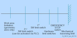
Overview of travel limits
Preceding the EMERGENCY-STOP switch, hardware limit switches, which take the form of digital inputs controlled via the PLC interface, limit the traversing range of the machine axes. Deceleration is effected either as rapid deceleration with setpoint zero or in accordance with a braking characteristic. The axes must be retracted in the opposite direction in JOG mode.
Software limit switches precede the hardware limit switches, are not overtraveled, and are not active until reference point approach has been completed.
Following preset, software limit switches are no longer effective. A second pair of plus/minus software limit switches can be activated via the PLC.
Linear interpolation
"Linear interpolation" is understood to be the CNC-internal calculation of points on a straight path between the programmed starting and end points.
Limited functionality of export control versions: The number of simultaneously interpolating axes is restricted to 4.
Look Ahead
> Continuous-path mode with programmable rounding clearance
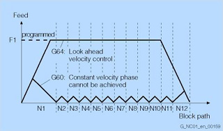
Comparison of velocity response with exact stop G60 and continuous-path mode G64 with look ahead for short displacements.
During the machining of complex contours, most of the resulting program blocks have very short paths with sharp changes in direction. If a contour of this type is processed with a fixed programmed path velocity, an optimum result cannot be obtained. In short traversing blocks with tangential block transitions, the drives cannot attain the required final velocity because of the short path distances. Contours are rounded when traveling around corners.
The Look Ahead function is a means of optimizing the machining speed by looking ahead over a parameterizable number of traversing blocks. With tangential block transitions, the axis is accelerated and decelerated beyond block boundaries, so that no drops in velocity occur. On sharp changes of direction, rounding of the contour is reduced to a programmable path dimension.
Look-ahead detection of contour violations
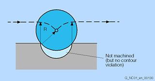
Behavior when tool radius > circle radius
With CDON (Collision Detection ON) and active tool radius compensation, the control monitors tool paths through look-ahead contour calculation. This makes it possible for the control to actively detect and avert possible collisions.
The control detects the following critical machining situations, for example when the tool radius is too large, and compensates through tool path modification.
- Bottleneck detection:
Because the tool radius is too large to produce a narrow inside contour, the bottleneck is bypassed and an alarm output. - Contour path shorter than tool radius:
The tool bypasses the workpiece corner on a transition circle, then continues on the programmed path. - Tool radius too large for internal machining:
In such cases, the contours are machined only as much as is possible without causing a contour violation.
Machining channels (option C11-C19)
> Mode group
Idle times can be shortened via a channel structure using parallel sequences of motion, such as moving a loading gantry during machining. A machining channel must be regarded as a separate CNC with decoding, block preparation and interpolation. The channel structure makes it possible to process the individual channels' part programs simultaneously and asynchronously. The relevant channel with the associated images is selected with the channel switchover button on the operator panel. Part programs can then be chosen and started for that specific channel. Each possible channel can run in a separate mode group. Additional machining channels are optional. One machining channel is available in the basic version. With the option C11-C19, the number can be increased to up to 10 machining channels.
Machining package 5 axes (option M30)
Universal milling head
Five-axis machining tasks, such as the milling of free-form surfaces, can be solved easily and in a user-friendly manner.
To this end, the "Machining package 5 axes" provides the following functions:
- 5-axis transformation with tool orientation
In 5-axis machining, geometric axes X, Y and Z are supplemented by additional axes (such as rotary axes for tilting the tool). The machining task can be completely defined in Cartesian spatial coordinates with Cartesian position and orientation. The path vector is converted in the control into the machine axes, including position and orientation, via 5-axis transformation. - 5-axis tool length compensation for 5-axis machining
When machining with the 4th/5th axis, the lengths of the selected tool are automatically included and compensated in the axis movement. - Oriented tool retraction
If machining is interrupted (because of tool breakage, for example), a program command can be used to carry out defined, oriented tool retraction. - Tool-oriented RTCP
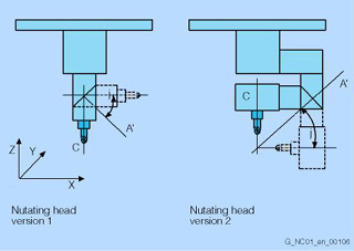
With the RTCP (remote tool center point) function, the tool swivel axes can be positioned in manual mode, as long as there is compliance with the tool center point marked by the tool tip. The RTCP function simplifies the inclusion of program interpolation points in manual mode with orientation of the tool. - Universal milling head/nutating head
Precondition: Machining package 5 axes with 5-axis transformation. Using a universal milling head in conjunction with the "nutating head" function, it is possible to machine outside contours of spatially formed parts at a high feedrate. To do this, the control executes a 5-axis transformation. Three translatory main axes (X, Y, Z) determine the tool operating point; two rotary axes, one of which is an inclined axis (angle can be set in the machine data), permit virtually any orientation in the working area. Version 1 and version 2 of the universal milling heads are supported. In the case of version 2, the position of the operating point does not change when the tool is swiveled; the compensating movements required for orientation changes are minimal. - Contains option Multi-axis interpolation (M15)
Limited functionality of export control versions: Not possible.
Machining package 5 axes, additional function 7th axis
(option S01)
In combination with "Machining package 5 axes", this option supports 7-axis interpolation. This means that redundant rotation of a workpiece is possible in the work space, with 5th/6th axis tool kinematics active at the same time. Application example: Fiber placement machines in aircraft assembly.
Machining package milling (option M26)
- 5-axis machining package
- Multi-axis interpolation
- Spline interpolation for 5-axis machining
- 3D tool offset
The milling machining package contains the following options: "5-axis machining package", "Multi-axis interpolation", "Spline interpolation for 5-axis machining", and "3D tool offset".
Limited functionality of export control versions: Not possible.
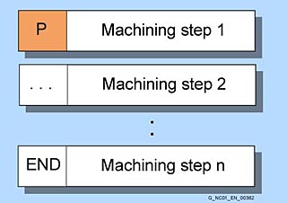
Machining step programming (option P04)
Machining steps are programmed graphically with a graphic, interactive machining step editor. In this case, each program line represents a machining step (e.g. face milling, centering, drilling, tapping) or geometric data required for the machining steps (pattern positions or contours). All required technical and geometric parameters are entered in screen forms. Simple, intuitive programming with machining steps can always be expanded very flexibly through input of DIN/ISO blocks.
Highlights:
- Intuitive program input, no DIN/ISO knowledge or operating manual required
- Compact, clearly arranged machining programs
- Reduction of programming time through graphical input screens, copying/inserting and linking machining steps
Main program call from main program and subprogram
If machining operations recur frequently, it is advisable to store them in a subprogram. The subprogram is called from a main program (number of passes 9999). Eleven subprogram levels (including three levels for interrupt routines) are possible in one main program. A main program can also be called from within another main program or subprogram.
Manual machine (option P11)
We offer the manual machine function for beginners switching over from conventional machines, but also for experienced CNC machine operators who often only use individual machining steps. The basic screen MANUAL is displayed immediately after booting the machine offering the direct machining options without having to create a part program.
Master value coupling and curve table interpolation (option M20)
> Measuring, stage 2; synchronous spindle
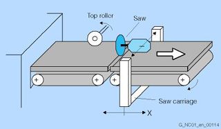
Example for cyclic machines: Flying saw
For special technologies (presses, transfer lines, printing machines, etc.), the replacement of mechanical, cyclic transport tasks with electronic functionality in AUTOMATIC mode requires constant coupling and decoupling functions between leading and following axes. To this end, the synchronous spindle function has been expanded to include the master value coupling function, which makes it possible for linear master and following axes to be coupled via curve tables in the CNC program.
Any function relations between axis positions can be approximated.
Soft coupling avoids the sudden change in velocity that occurs when the master axis is activated. Offsets (e.g., 12°), scalings (e.g., 1.00023) and mirroring using frame instructions are possible.
Electronic curve table interpolation replaces the cam discs that were once required for the control of cyclic machines.
Complex sequences of motion can be easily defined using familiar CNC language elements. The external reference variable (e.g., "line shaft") is formed by the control's master value. The functional relation between leading and following axis can be subdivided into segments of the master axis (curve segments). In these curve segments, the link between master value and following value is described using mathematical functions (normally through 3rd degree polynomials).
Cyclic machines are distinguished by constantly repeated cyclic operations with high throughput and high productivity in machining, transport, packaging and parts handling (for example, packaging machines, presses, woodworking machines, printing machines).
With SINUMERIK, technological functions such as synchronism, electronic transfer and positioning for cyclic machines can be implemented. Mechanics (line shaft, gearing, cam discs, couplings and cams) are replaced by an electronic solution (master value coupling, curve tables, synchronous actions, and electronic cams).
In addition, the electronic functionality permits fast, axis-specific optimization, high-speed phase and path compensation, fast responses to faulty or missing parts, and fast synchronization and resynchronization, as well as decoupling from the master axis and executing autonomous movements.
Axis cycles and synchronization calculations are carried out in the IPO cycle.
Measuring from synchronous actions, for example, is used for detecting edges on continuous workpieces and for measuring pressure marks (on continuous films, for example).
Limited functionality of export control versions: The number of simultaneously traversing axes is restricted to 4.
Master/slave for drives (option M03)
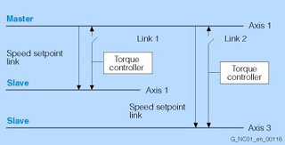
Example: Axis 1 is simultaneously the master axis for axis 2 and axis 3
The "master/slave for drives" function is required when two electrical drives are mechanically linked to an axis. With this link, a torque controller ensures that both drives produce the exact same amount of torque, so that the motors do not work in opposition. In order to attain tensioning between the master and slave drives, a tension torque specifiable via machine data can be applied on the torque controller.
Application examples:
- Performance enhancement and (occasional) mechanical coupling of drives
- Drive with 2 motors that operate on a gear rack
- Remachining of wheel sets for rail-bound vehicles
- Zero backlash reversing of mutually tensioned drives
An axis can also be a master axis for multiple couplings.
Measure kinematics (option P18)
The "Measure kinematics" function supports the calibration of kinematic structures of 5-axis machines. The SINUMERIK 840D sl is now able to determine the parameters of kinematic transformations of the digitally or manually alignable rotary axes quickly and automatically. The function is ideal for initial startup, because a dimensioned drawing of the machine is not required. The function can also be used for regular checking of the production process, when high precision is required.
Measuring cycles (option P28)
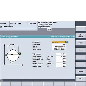
Example: Measuring a shaft
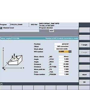
Example: Two angle measurement for determining the position of a plane in space
In the case of tool measuring, the loaded tool (typically in the revolver on turning machines) is moved towards the probe which is either in a fixed position or swiveled into the working range by a mechanical device. The automatically derived tool geometry is entered in the relevant tool offset data record.
In the case of workpiece measuring, a probe is moved towards the clamped workpiece like a tool. The flexible selection of measuring cycles means that you can handle practically every measuring task associated with turning or milling.
The principle of "on-the-fly measurement" is used in SINUMERIK controls. The advantage of this principle is that the probe signal is processed directly in the CNC. The measuring parameters and the results of the measurements are output extremely clearly in separate displays which are either automatically deselected at the end of the cycle, or can be acknowledged when starting the CNC.
The result of the workpiece measurement can either include automatic offset of the zero point or a correction of the tool wear by the difference between the actual value and the setpoint. The measured results can be logged in a file. The Siemens measuring cycles offer a standard log which you can also adapt.
In order to measure tool and workpiece dimensions, a touch-trigger probe is required that supplies a constant signal (rather than a pulse) when deflected. The probe should switch bounce-free, and mechanical adjustment may be necessary.
Multidirectional probes can be used for all tool and workpiece measurements on turning and milling machines. Bidirectional probes are treated like a mono probe for workpiece measurements on milling and machining centers, but are not suitable for tool measurements.
Monodirectional probes can be used on milling machines and machining centers with slight restrictions in workpiece measurements, but are not suitable for tool measurements or for workpiece measurements on turning machines.
Measuring Cycles for Turning Machines
- Tool measurements (calibration/measurement) for turning tools
- Tool measurements for milling tools and drills on turning machines
- Calibrating workpiece probes
- 1-point workpiece measurement
- 2-point workpiece measurement
Measuring cycles for milling machines and machining centers
- Tool measurements (calibration/measurement) for milling tools
- Calibrating workpiece probes
- Paraxial workpiece measurement on hole/shaft/slot/web/rectangle
- 1-point workpiece measurement on area
- Workpiece measurement at any angle on hole/shaft/slot/web
- Workpiece measurement at angular position (1-/2-angle measurement)
- Automatic set-up corner internal and external
- Measurement of workpiece sphere and automatic correction of work offset
Measuring functions/measuring cycles
Measuring functions can execute either channel-specifically including all axes programmed in the measuring set as well as axially from the parts program or from synchronous actions beyond NC block limits.
Measuring cycles are subprograms for implementing specific measuring tasks on tools or workpieces. They are easy to use and simply require the input of values in predefined parameters.
- Measuring in JOG
- 2 probes can be connected simultaneously
- Measurement in space with frame
- Adaptable measuring modes with/without deletion of distance to go
- Display and logging of measuring parameters and results (with measuring cycles)
- Results can be read in the machine or workpiece coordinate system
- Cyclic measurement with synchronized actions parallel to workpiece machining
With the advantages of the measuring functions and measuring cycles, the machining accuracy is assured, unproductive time is reduced, sources of error are dispensed with and the manufacturing process is automated further.
Measuring stage 1
You can connect up to two switching touch probes to the control at the same time. In the case of channel-specific measuring, the measuring process for a CNC channel is always activated from the part program running in the relevant channel. All of the axes programmed in the measuring block take part in the measuring process.
You can program a trigger event (rising or falling edge) and a measuring mode (with or without deletion of the residual path) for each measuring process.
The results of measurements can be read in the part program or with synchronous actions in both the machine and the workpiece coordination system. You can test the deflection of the touch probe by scanning a variable and outputting it to the PLC interface and deriving responses in the part program. The option Measuring stage 2 (option M32) provides you with expanded functionality (for example for axial measuring, evaluating up to 4 trigger events, and cyclic measuring).
Measuring stage 2 (option M32)
While the measuring function in motion blocks in the part program is limited to one block, you can activate measuring functions from synchronous actions at any time, independent of the part program. The measuring events can be assigned to the axes in the CNC block. In the case of simultaneous measuring, up to 4 trigger events can be evaluated per position control cycle. Measured values are read as a function of the three parameters: touch probe, axis and measuring edge.
In the case of continuous (cyclic) measuring, the measurement results are written to a FIFO variable. Endless measuring can be achieved by reading out the FIFO values cyclically.
Measurement results can be logged in the form of a file. The measuring cycles (option P28) contain a standard log, which can be configured as the user wishes.
Measuring system 1 and 2, selectable
For special applications, two encoders can be assigned to one axis, e.g., a direct measuring system for the machining process with high demands on accuracy, and an indirect measuring system for high-speed positioning tasks. The switchover between measuring systems 1 and 2 is performed via the PLC.
Measuring system error compensation
> Leadscrew error compensation / measuring system error compensation
Mode group (option C01-C09)
A mode group combines CNC channels with axes and spindles to form a machining unit.
A mode group contains channels that must always be in the same mode at the same time during the machining sequence. Within a mode group, every axis can be programmed in every channel. A mode group can be regarded as an independent, multi-channel CNC.
One mode group is available in the basic version. With the option C01-C09, the number can be increased to up to 10 mode groups.
Monitoring for maximum tool speed/acceleration (option S08)
Two parameters within the tool data can be used to specify the maximum speed and maximum acceleration of a tool. If the tool is in the spindle, the speed or the acceleration of the spindle are limited to these values. The limits can be separately activated and set. The speed is limited to the permissible value, even if the specified setpoint speed would be exceeded by more than 100 % through the override switch.
Monitoring functions
The controls contain watchdog monitors, which are always active. These monitors detect faults in the CNC, PLC or machine in time to prevent damage to workpiece, tool or machine. When a fault occurs, the machine operation is interrupted and the drives brought to a standstill.
The cause of the fault is saved and displayed as an alarm. At the same time, the PLC is notified that a CNC alarm has been triggered.
Monitoring functions exist for the following areas:
- Read in
- Format
- Encoder and drive
- Contour
- Position
- Standstill
- Clamping
- Speed setpoint
- Actual velocity
- Enabling signals
- Voltage
- Temperatures
- Microprocessors
- Serial interfaces
- Transfer between CNC and PLC
- Backup battery voltage
- System memory and user memory
Motion-synchronous actions
> Synchronized actions
Multi-axis interpolation (> 4 interpolating axes) (option M15)
The number of interpolating axes can be expanded and is limited by option and machine data as well as by the number of axes available in the channel.
Limited functionality of export control versions: Not possible.
Multi-channel display
In the machine operating area, the M key can be used to select either single-channel or multi-channel display. In the multi-channel display, only channel information is displayed; the channel can be operated or influenced in the single-channel display. Focus switching, scroll bars and window selection can be operated in the multi-channel display, but it is not possible to change the NC channel data. The same windows are always displayed together in all channels. The softkeys for switching the windows, therefore, always affect all the channels that are on display. In the multi-channel display, the axis actual values are displayed in the top window and the selection menus (T/F/S values, program blocks) in the bottom window, depending on which of the softkeys is activated.
Multiple clamping of various workpieces (option P14)
Several identical workpieces can be clamped onto the machine table. With the multiple clamping function, an entire program is generated from the graphic program of the relevant single machining operation. The machining steps are sorted in this program so that the number of tool changes (and thus idle times) is reduced to a minimum.
This function allows similar and different workpieces to be finished on multiple vises or gripping yokes, while saving time.
Multiple feedrates in one block
Depending on external digital and/or analog inputs, this function can be used for motion-synchronous activation of up to 6 different feedrates, a dwell time, and a retraction in a single CNC block. The input signals are combined in an input byte with a permanently assigned function. The retraction is initiated by an amount defined in advance within an IPO cycle. Retraction movement or dwell time (e.g., sparking-out time during grinding) lead to deletion of the distance-to-go.
Typical applications involve analog or digital calipers or a change from infeed feedrate to machining feedrate via proximity switches. During internal grinding of a ball bearing ring, for instance, in which calipers are used to measure the actual diameter, the feedrate value required for roughing, finishing or smooth-finishing can be activated depending on threshold values.
Number of subprogram repetitions
In order to execute a subprogram several times in succession, the desired number of program repetitions can be programmed in the block with the subprogram call at address P (range of values: 1 to 9999).
Parameters are transferred only when the program is called or in the first pass. The parameters remain the same for all repetitions. If you want to change the parameters between passes, you should make the relevant declarations in the subprogram.