|
| | | | | |
?
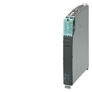
Double Motor Modules feature the following connections and interfaces as standard:
- 2 DC link connections via integrated DC link busbars
- 2 ? electronic power supply connections via integrated 24 V DC bars
- 4 DRIVE?CLiQ sockets
- 2 plug-in motor connections (not included in scope of supply)
- 2 safe standstill inputs (1 input per axis)
- 2 safe motor brake controller
- 2 temperature sensor inputs (KTY84-130 or PTC)
- 3 PE/protective conductor connections
The status of the Motor Modules is indicated via two multi-color LEDs.
On Double Motor Modules, the motor cable shield can be connected in the connector.
The signal cable shield can be connected to the Motor Module by means of a terminal element, e.g. Weidmuller type KLBU 3-8 SC.
The scope of supply of the Motor Modules includes:
- DRIVE?CLiQ cable (length depends on module width) to connect Motor Module to adjacent Motor Module
- 2 blanking plugs for closing unused DRIVE?CLiQ sockets
- Jumper for connecting the 24 V DC busbar to the adjacent Motor Module
- Connectors X21 and X22
- Device fans for cooling power units on modules with internal and external air cooling supplied from the internal voltage levels
- 1 set of warning signs in 30 languages
- 1 heat conducting foil (for Double Motor Modules with cold plate cooling only)
|
