
Deprecated: Function eregi() is deprecated in /home/h101150-2/siemens71.ru/docs/new/cat.php on line 184
|
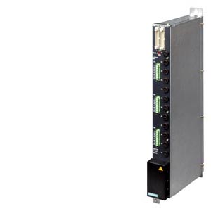
LA724I HP power output module |
|
|
Outputs per power output module |
12 |
|
Galvanic isolation from control unit |
By means of opto-triac and optocoupler specified according to EN 60747-5-2 |
|
Insulation voltage |
|
|
5 kV |
|
5.3 kV |
|
Galvanic isolation of power outputs from each other |
no |
|
Load voltage (for star and delta circuit configuration) |
|
|
230/400 V AC |
|
187 ... 264 V, 340 ... 460 V AC (TN system) |
|
50/60 Hz (47 ... 63 Hz) |
|
Max. total current per phase and module |
40 A |
|
Current per busbar, max. |
120 A |
|
Output voltage |
Full or half-waves switched during zero crossing |
|
Output current |
|
|
10 A (fusing is carried out with a fuse of type 16 A slow blow/500 V; the connecting cable must be dimensioned accordingly) |
|
7 mA |
|
Power loss |
Typ.PV = 0.7 W/A x I + 0.16 W/A2 x I2 |
|
Switching capacity (100% simultaneity) |
2,300 W per channel at 230 V Note: The total current per phase must not exceed 40 A. Min. 75 W per channel |
|
Parallel connection of heat emitters to one channel |
|
|
5 |
|
200 W |
|
Total switching capacity per LA724I HP power output module (TU = 40 °C) |
|
|
13/22.6 kW (star/delta) |
|
21/36.5 kW (star/delta) |
|
Load type |
Resistive load with a maximum of 15 times the cold current in the first half wave. (In the case of flash emitters, this can lead to a reduction of the permissible switching capacity. These emitters can be measured at Siemens.) |
|
Overload |
5 times the rated current for 20 ms |
|
Protective measures |
|
|
Yes (by NTC thermistor) 92 °C ± 3 °C: Alarm to higher-level controller via PROFIBUS DP 100 °C ± 3 °C: Deactivation of the power output modules |
|
One 16 A/ 250 V fuse per output |
|
By Transil diodes |
|
Connecting cable |
R
max = 14 W |
|
Dimensions (W x H x D) |
50 mm x 480 mm x 210 mm |
|
Weight, approx. |
Approx. 5.3 kg |