
Operation of electronics with HART communication
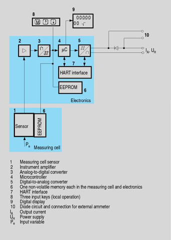
Function diagram of electronics
The bridge output voltage created by the sensor (1, Figure "Function diagram of electronics") is amplified by the measuring amplifier (2) and digitized in the analog-to-digital converter (3). The digital information is evaluated in a microcontroller, its linearity and temperature response corrected, and converted in a digital-to-analog converter (5) into an output current of 4 to 20 mA.
The diode circuit (10) protects against incorrect polarity.
The data specific to the measuring cell, the electronics data, and the parameter data are stored in the two non-volatile memories (6). The one memory is coupled to the measuring cell, the other to the electronics. As the result of this modular design, the electronics and the measuring cell can be replaced separately from each other.
Using the 3 input keys (8) you can parameterize the pressure transmitter directly at the measuring point. The input buttons can also be used to control the view of the results, the error messages and the operating modes on the display (9).
The HART modem (7) permits parameterization using a protocol according to the HART specification.
The pressure transmitters with spans 63 bar measure the input pressure compared to atmosphere, transmitters with spans 160 bar compared to vacuum.
Operation of electronics with PROFIBUS PA communication
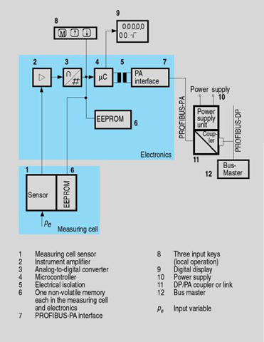
Function diagram of electronics
The bridge output voltage created by the sensor (1, Figure "Function diagram of electronics") is amplified by the measuring amplifier (2) and digitized in the analog-to-digital converter (3). The digital information is evaluated in the microcontroller, its linearity and temperature response corrected, and provided on the PROFIBUS PA through an electrically isolated PA interface (7).
The data specific to the measuring cell, the electronics data, and the parameter data are stored in the two non-volatile memories (6). The one memory is coupled to the measuring cell, the other to the electronics. As the result of this modular design, the electronics and the measuring cell can be replaced separately from each other.
Using the three input buttons (8) you can parameterize the pressure transmitter directly at the measuring point. The input buttons can also be used to control the view of the results, the error messages and the operating modes on the display (9).
The results with status values and diagnostic values are transferred by cyclic data transmission on the PROFIBUS PA. Parameterization data and error messages are transferred by acyclic data transmission. Special software such as SIMATIC PDM is required for this.
Operation of electronics with FOUNDATION Fieldbus communication
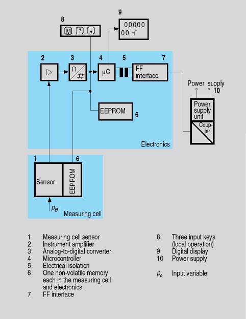
Function diagram of electronics
The bridge output voltage created by the sensor (1, Figure "Function diagram of electronics") is amplified by the measuring amplifier (2) and digitized in the analog-to-digital converter (3). The digital information is evaluated in the microcontroller, its linearity and temperature response corrected, and provided on the FOUNDATION Fieldbus through an electrically isolated FOUNDATION Fieldbus interface (7).
The data specific to the measuring cell, the electronics data, and the parameter data are stored in the two non-volatile memories (6). The one memory is coupled to the measuring cell, the other to the electronics. As the result of this modular design, the electronics and the measuring cell can be replaced separately from each other.
Using the three input buttons (8) you can parameterize the pressure transmitter directly at the measuring point. The input buttons can also be used to control the view of the results, the error messages and the operating modes on the display (9).
The results with status values and diagnostic values are transferred by cyclic data transmission on the FOUNDATION Fieldbus. Parameterization data and error messages are transferred by acyclic data transmission. Special software such as National Instruments Configurator is required for this.
Mode of operation of the measuring cells
Measuring cell for gauge pressure
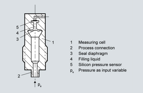
Measuring cell for gauge pressure, function diagram
The pressure pe is applied through the process connection (2, Figure "Measuring cell for gauge pressure, function diagram") to the measuring cell (1). This pressure is subsequently transmitted further through the seal diaphragm (3) and the filling liquid (4) to the silicon pressure sensor (5) whose measuring diaphragm is then flexed. This changes the resistance of the four piezo-resistors fitted in the diaphragm in a bridge circuit. This change in resistance results in a bridge output voltage proportional to the absolute pressure.
Measuring cell for gage pressure with flush-mounted diaphragm
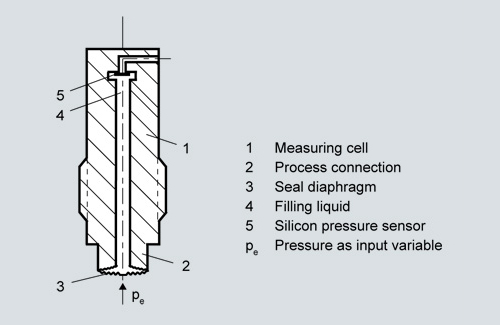
Measuring cell for gage pressure, with flush-mounted diaphragm for paper industry, function diagram
The pressurepe is applied through the process connection (2, Figure "Measuring cell for gage pressure, with flush-mounted diaphragm for paper industry, function diagram") to the measuring cell (1). This pressure is subsequently transmitted further through the seal diaphragm (3) and the filling liquid (4) to the silicon pressure sensor (5) whose measuring diaphragm is then flexed. This changes the resistance of the four piezo-resistors fitted in the diaphragm in a bridge circuit. This change in resistance results in a bridge output voltage proportional to the absolute pressure.
Measuring cell for absolute pressure from gauge pressure series
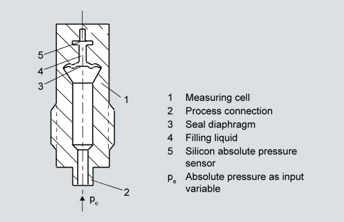
Measuring cell for absolute pressure from the pressure series, function diagram
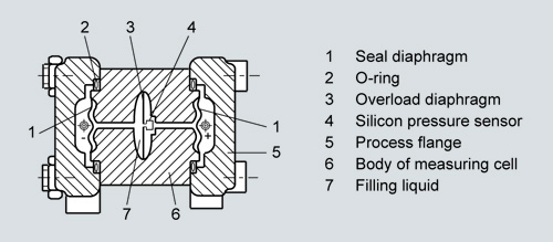
The absolute pressurepe is transmitted through the seal diaphragm (3, Figure "Measuring cell for absolute pressure from pressure series, guage pressure, function diagram") and the filling liquid (4) to the silicon absolute pressure sensor (5) whose measuring diaphragm is then flexed. This changes the resistance of the four piezo-resistors fitted in the diaphragm in a bridge circuit. This change in resistance results in a bridge output voltage proportional to the absolute pressure.
Measuring cell for absolute pressure from differential pressure series
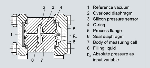
Measuring cell for absolute pressure from differential pressure series, function diagram
The input pressure pe is transmitted through the seal diaphragm (6, Figure "Measuring cell for absolute pressure from differential pressure series, function diagram") and the filling liquid (8) to the silicon pressure sensor (3).
The difference in pressure between the input pressure pe and the reference vacuum (1) on the low-pressure side of the measuring cell flexes the measuring diaphragm. This changes the resistance of the four piezo-resistors fitted in the diaphragm in a bridge circuit. This change in resistance results in a bridge output voltage proportional to the absolute pressure.
An overload diaphragm is installed to provide protection from overloads. If the measuring limits are exceeded, the overload diaphragm (2) is flexed until the seal diaphragm rests on the body of the measuring cell (7), thus protecting the silicon pressure sensor from overloads.
Measuring cell for differential pressure and flow
Measuring cell for differential pressure and flow, function diagram
The differential pressure is transmitted through the seal diaphragms (1, Figure "Measuring cell for differential pressure and flow, function diagram") and the filling liquid (7) to the silicon pressure sensor (4).
The measuring diaphragm is flexed by the applied differential pressure. This changes the resistance of the four piezo-resistors fitted in the diaphragm in a bridge circuit. This change in resistance results in a bridge output voltage proportional to the absolute pressure.
An overload diaphragm is installed to provide protection from overloads. If the measuring limits are exceeded, the overload diaphragm (2) is flexed until the seal diaphragm rests on the body of the measuring cell (7), thus protecting the silicon pressure sensor from overloads.
Measuring cell for level
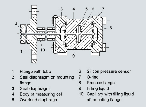
Measuring cell for level, function diagram
The input pressure (hydrostatic pressure) acts hydraulically on the measuring cell through the seal diaphragm on the mounting flange (2, Figure "Measuring cell for level, function diagram"). This differential pressure is subsequently transmitted further through the measuring cell (3) and the filling liquid (9) to the silicon pressure sensor (6) whose measuring diaphragm is then flexed.
This changes the resistance of the four piezo-resistors fitted in the diaphragm in a bridge circuit.
This change in resistance results in a bridge output voltage proportional to the differential pressure.
An overload diaphragm is installed to provide protection from overloads. If the measuring limits are exceeded, the overload diaphragm (2) is flexed until the seal diaphragm rests on the body of the measuring cell (7), thus protecting the silicon pressure sensor from overloads.
Parameterization DS III
Depending on the version, there are a range of options for parameterizing the pressure transmitter and for setting or scanning the parameters.
Parameterization using the input buttons (local operation)
With the input buttons you can easily set the most important parameters without any additional equipment.
Parameterization using HART
Parameterization using HART is performed with a HART Communicator or a PC.
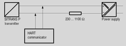
Communication between a HART Communicator and a pressure transmitter
When parameterizing with the HART Communicator, the connection is made directly to the 2-wire cable.
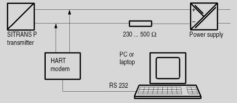
HART communication between a PC communicator and a pressure transmitter
When parameterizing with a PC, the connection is made through a HART modem.
The signals needed for communication in conformity with the HART 5.x or 6.x protocols are superimposed on the output current using the Frequency Shift Keying (FSK) method.
Adjustable parameters, DS III with HART
|
Parameters |
Input keys (DS III with HART) |
HART communication |
|---|---|---|
|
Start of scale |
x |
x |
|
Full-scale value |
x |
x |
|
Electrical damping |
x |
x |
|
Start-of-scale value without application of a pressure ("Blind setting") |
x |
x |
|
Full-scale value without application of a pressure ("Blind setting") |
x |
x |
|
Zero adjustment |
x |
x |
|
current transmitter |
x |
x |
|
Fault current |
x |
x |
|
Disabling of buttons, write protection |
x |
x 1) |
|
Type of dimension and actual dimension |
x |
x |
|
Characteristic (linear / square-rooted) |
x 2) |
x 2) |
|
Input of characteristic |
x |
|
|
Freely-programmable LCD |
x |
|
|
Diagnostic functions |
x |
1) Cancel apart from write protection
2) Only differential pressure
Diagnostic functions for DS III with HART
- Zero correction display
- Event counter
- Limit transmitter
- Saturation alarm
- Slave pointer
- Simulation functions
- Maintenance timer
Available physical units of display for DS III with HART
Table style: Technical specifications 2
|
Physical variable |
Physical dimensions |
|
Pressure (setting can also be made in the factory) |
Pa, MPa, kPa, bar, mbar, torr, atm, psi, g/cm2, kg/cm2, inH2O, inH2O (4 °C), mmH2O, ftH2O (20 °C), inHg, mmHg |
|
Level (height data) |
m, cm, mm, ft, in |
|
Volume |
m3, dm3, hl, yd3, ft3, in3, US gallon, lmp. gallon, bushel, barrel, barrel liquid |
|
Mass |
g, kg, t, lb, Ston, Lton, oz |
|
volume flow |
m3/d, m3/h, m3/s, l/min, l/s, ft3/d, ft3/min, ft3/s, US gallon/min, US gallon/s |
|
Mass flow |
t/d, t/h, t/min, kg/d, kg/h, kg/min, kg/s, g/d, g/h, g/min, g/s, lb/d, lb/h, lb/min, lb/s, LTon/d, LTon/h, STon/d, STon/h, STon/min |
|
Temperature |
K, °C, °F, °R |
|
Miscellaneous |
%, mA |
Parameterization through PROFIBUS PA interface
Fully digital communication through PROFIBUS PA, profile 3.0, is particularly user-friendly. Through the PROFIBUS the DS III with PROFIBUS PA is connected to a process control system, e. g. SIMATIC PSC 7. Communication is possible even in a potentially explosive environment.
For parameterization through PROFIBUS you need suitable software, e. g. SIMATIC PDM (Process Device Manager)
Parameterization through FOUNDATION Fieldbus interface
Fully digital communication through FOUNDATION Fieldbus is particularly user-friendly. Through the FOUNDATION Fieldbus the DS III with FOUNDATION Fieldbus is connected to a process control system. Communication is possible even in a potentially explosive environment.
For parameterization through the FOUNDATION Fieldbus you need suitable software, e. g. National Instruments Configurator.
Adjustable parameters for DS III with PROFIBUS PA and FOUNDATION Fieldbus
|
Parameters |
Input buttons |
PROFIBUS PA and FOUNDATION Fieldbus interface |
|---|---|---|
|
Electrical damping |
x |
x |
|
Zero adjustment (correction of position) |
x |
x |
|
Buttons and/or function disabling |
x |
x |
|
Source of measured-value display |
x |
x |
|
Physical dimension of display |
x |
x |
|
Position of decimal point |
x |
x |
|
Bus address |
x |
x |
|
Adjustment of characteristic |
x |
x |
|
Input of characteristic |
x |
|
|
Freely-programmable LCD |
x |
|
|
Diagnostics functions |
x |
Diagnostic functions for DS III with PROFIBUS PA and FOUNDATION Fieldbus
- Event counter
- Slave pointer
- Maintenance timer
- Simulation functions
- Display of zero correction
- Limit transmitter
- Saturation alarm
Physical dimensions available for the display
|
Physical variable |
Physical dimensions |
|
Pressure (setting can also be made in the factory) |
MPa, kPa, Pa, bar, mbar, torr, atm, psi, g/cm2, kg/cm2, mmH2O, mmH2O (4 °C), inH2O, inH20 (4 °C), ftH2O (20 °C), mmHg, inHg |
|
Level (height data) |
m, cm, mm, ft, in, yd |
|
Volume |
m3, dm3, hl, yd3, ft3, in3, US gallon, lmp. gallon, bushel, barrel, barrel liquid |
|
volume flow |
m3/s, m3/min, m3/h, m3/d, l/s, l/min, l/h, l/ d, Ml/d, ft3/s, ft3/min, ft3/h, ft3/d, US gallon/s, US gallon/min, US gallon/h, US gallon/d, bbl/s, bbl/min, bbl/h, bbl/d |
|
Mass flow |
g/s, g/min, g/h, g/d, kg/s, kg/min, kg/h, kg/d, t/s, t/min, t/h, /t/d, lb/s, lb/min, lb/h, lb/d, STon/s, STon/min, STon/h, STon/d, LTon/s, LTon/min, LTon/h, LTon/d |
|
Total mass flow |
t, kg, g, lb, oz, LTon, STon |
|
Temperature |
K, °C, °F, °R |
|
Miscellaneous |
% |