

Electrical connections
Non-EEx version: connection cable - customer interface
|
Terminal block in the receiver enclosure |
Function/voltage |
Ethernet cable |
||
|---|---|---|---|---|
|
1 |
+ |
Power supply |
||
|
2 |
- |
|||
|
3 |
Normally closed under power4) |
Binary output 0 (relay) |
||
|
4 |
||||
|
5 |
Normally closed under power4) |
Binary output 1 (relay) |
||
|
6 |
||||
|
7 |
+ |
Binary input 0 |
||
|
8 |
- |
|||
|
9 |
+ |
Analog output 0 (measurement) |
||
|
10 |
- |
|||
|
11 |
+ |
Analog output 1 (measurement) |
||
|
12 |
- |
|||
|
13 |
PROFIBUS A line (RxD/TxD_N - data inverted) |
Modbus D1 (RxD/TxD_N - data inverted) |
RS 485 -7 ... +12 V DC |
|
|
14 |
PROFIBUS B line (RxD/TxD_P - data not inverted) |
Modbus D0 (RxD/TxD_P - data not inverted) |
||
|
15 |
PROFIBUS/Modbus shield |
|||
|
16 |
Tx+ |
Ethernet5) |
White/orange |
|
|
17 |
Tx- |
Orange |
||
|
18 |
Rx+ |
White/green |
||
|
19 |
Rx- |
Green |
||
|
20 |
+ |
Analog input 0 (temperature) |
||
|
21 |
- |
|||
|
22 |
+ |
Analog input 1 (pressure) |
||
|
23 |
- |
|||
|
24 |
Grounding |
|||
|
25 |
Grounding |
|||
|
Ground |
Grounding |
|||
|
Ground |
Grounding |
Shielding |
||
1) This is the maximum power consumption of the SITRANS SL
2) These are the maximum input values
3) These are the maximum output values
4) Note:
"Normal operation" stands for normal operation of the analyzer. The system is connected to the voltage source and is running without problems; no error message generated or displayed.
"Normal under power" refers to the status of the relay under the above-named normal operation. The relay contact of the alarm signal is closed.
5) We recommend that the Ethernet connection is not made via the cable to the Ethernet terminals in the detector unit. Instead, the Ethernet connection should be made via the sensor cable connection set which is optionally available for the detector unit.
Examples of digital output and analog output
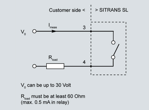
Example of digital output 0
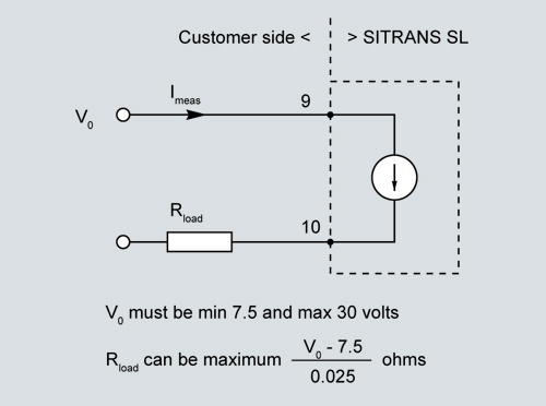
Example of analog output 0,
caution: please note that an external isolating power supply may be required!
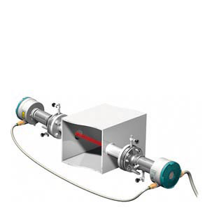
Sensor cable terminal box on the receiver side (ATEX version)
|
Terminal strip in terminal box |
Function |
Color code |
|
|---|---|---|---|
|
1 |
+ |
24 V DC voltage supply |
Red |
|
2 |
- |
Blue |
|
|
3 |
Com + |
Communication with transmitter |
Pink |
|
4 |
Com - |
Gray |
|
|
5 |
Sync + |
Synchronization with transmitter |
White |
|
6 |
Sync - |
Brown |
|
|
7 |
NC |
Not used |
- |
|
8 |
Tx+ |
Ethernet |
Gray/pink |
|
9 |
Tx- |
Red/blue |
|
|
10 |
Rx+ |
Black |
|
|
11 |
Rx- |
Violet |
|
|
PE terminal |
- |
Grounding |
Green |
|
PE terminal |
Grounding |
Yellow |
|
|
Gland |
Grounding |
Shielding |
|