
Principle of operation
In contrast to almost all other gases, oxygen is paramagnetic. This property is utilized as the measuring principle by the OXYMAT 6 gas analyzers.
Oxygen molecules in an inhomogeneous magnetic field are drawn in the direction of increased field strength due to their paramagnetism. When two gases with different oxygen contents meet in a magnetic field, a pressure difference is produced between them.
In the case of OXYMAT 6, one gas (1) is a reference gas (N2, O2 or air), the other is the sample gas (5). The reference gas is introduced into the sample chamber (6) through two channels (3). One of these reference gas streams meets the sample gas within the area of a magnetic field (7). Because the two channels are connected, the pressure, which is proportional to the oxygen content, causes a cross flow. This flow is converted into an electric signal by a microflow sensor (4).
The microflow sensor consists of two nickel-plated grids heated to approximately 120 C, which, along with two supplementary resistors, form a Wheatstone bridge. The pulsating flow results in a change in the resistance of the Ni grids. This leads to an offset in the bridge which is dependent on the oxygen concentration of the sample gas.
Because the microflow sensor is located in the reference gas stream, the measurement is not influenced by the thermal conductivity, the specific heat or the internal friction of the sample gas. This also provides a high degree of corrosion resistance because the microflow sensor is not exposed to the direct influence of the sample gas.
By using a magnetic field with alternating strength (8), the effect of the background flow in the microflow sensor is not detected, and the measurement is thus independent of the instrument's operating position.
The sample chamber is directly in the sample path and has a small volume, and the microflow sensor is a low-lag sensor. This results in a very short response time for the OXYMAT 6.
Vibrations frequently occur at the place of installation and may falsify the measured signal (noise). A further microflow sensor (10) through which no gas passes acts as a vibration sensor. Its signal is applied to the measured signal as compensation.
If the density of the sample gas deviates by more than 50 % from that of the reference gas, the compensation microflow sensor (10) is flushed with reference gas just like the measuring sensor (4).
Note
The sample gases must be fed into the analyzers free of dust. Condensation should be prevented from occurring in the sample chambers. Therefore, the use of gas modified for the measuring task is necessary in most application cases.
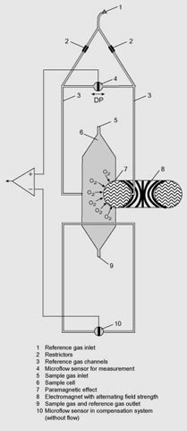
OXYMAT 6, principle of operation
Advantages of the function-based application of reference gas
- The zero point can be defined specific to the application. It is then also possible to set "physically" suppressed zero points. For example, it is possible when using pure oxygen as the zero gas to set a measuring range of 99.5 to 100 % O2 with a resolution of 50 ppm.
- The sensor (microflow sensor) is located outside the sample gas. Through use of an appropriate material in the gas path this also allows measurements in highly corrosive gases.
- Pressure variations in the sample gas can be compensated better since the reference gas is subjected to the same fluctuations.
- No influences on the thermal conductivity of the sample gas since the sensor is positioned on the reference gas side.
- The same gas is used for the serial gas calibration and as the reference gas. As a result of the low consumption of reference gas (3 to 10 ml/min), one calibration cylinder can be used for both gases.
- No measuring effect is generated in the absence of oxygen. The measured signal need not therefore be set electronically to zero, and is thus extremely stable with regard to temperature and electronic influences.
Essential characteristics
- Four freely parameterizable measuring ranges, also with suppressed zero point, all measuring ranges linear
- Measuring ranges with physically suppressed zero point possible
- Measuring range identification
- Galvanically isolated measured-value output 0/2/4 to 20 mA (also inverted)
- Autoranging possible; remote switching is also possible
- Storage of measured values possible during adjustments
- Wide range of selectable time constants (static/dynamic noise suppression); i.e. the response time of the analyzer can be matched to the respective measuring task
- Short response time
- Low long-term drift
- Measuring point switchover for up to 6 measuring points (programmable)
- Measuring point identification
- Internal pressure sensor for correction of pressure variations in sample gas range 500 to 2 000 hPa (abs.)
- External pressure sensor - only with piping as the gas path - can be connected for correction of variations in the sample gas pressure up to 3 000 hPa absolute (option)
- Monitoring of sample gas flow (option for version with hoses)
- Monitoring of sample gas and/or reference gas (option)
- Monitoring of reference gas with reference gas connection 3 000 to 5 000 hPa (abs.) (option)
- Automatic, parameterizable measuring range calibration
- Operation based on the NAMUR recommendation
- Two control levels with their own authorization codes for the prevention of accidental and unauthorized operator interventions
- Simple handling using a numerical membrane keyboard and operator prompting
- Customer-specific analyzer options such as:
- Customer acceptance
- TAG labels
- Drift recording
- Clean for O2 service
- Kalrez gaskets
- Analyzer unit with flow-type compensation branch: a flow is passed through the compensation branch (option) to reduce the vibration dependency in the case of highly different densities of the sample and reference gases
- Sample chamber for use in presence of highly corrosive sample gases
Reference gases
|
Measuring range |
Recommended reference gas |
Reference gas connection pressure |
Remarks |
|---|---|---|---|
|
0 to ... vol.% O2 |
N2 |
2 000 … 4 000 hPa above sample gas pressure (max. 5 000 hPa absolute) |
The reference gas flow is set automatically to 5 … 10 ml/min (up to 20 ml/min with flow-type compensation branch) |
|
... to 100 vol.% O2 (suppressed zero point with full-scale value 100 vol.% O2) |
O2 |
||
|
Around 21 vol.% O2 (suppressed zero point with 21 vol.% O2 within the measuring span) |
Air |
100 hPa with respect to sample gas pressure which may vary by max. 50 hPa around the atmospheric pressure |
Table 1: Reference gases for OXYMAT 6
Correction of zero point error / cross-sensitivities
|
Accompanying gas (concentration 100 vol. %) |
Deviation from zero point in vol. % O2 absolute |
Accompanying gas (concentration 100 vol. %) |
Deviation from zero point in vol. % O2 absolute |
|---|---|---|---|
|
Organic gases |
Inert gases |
||
|
Ethane C2H6 |
-0.49 |
Helium He |
+0.33 |
|
Ethene (ethylene) C2H4 |
-0.22 |
Neon Ne |
+0.17 |
|
Ethine (acetylene) C2H2 |
-0.29 |
Argon Ar |
-0.25 |
|
1.2 butadiene C4H6 |
-0.65 |
Krypton Kr |
-0.55 |
|
1.3 butadiene C4H6 |
-0.49 |
Xenon Xe |
-1.05 |
|
n-butane C4H10 |
-1.26 |
||
|
iso-butane C4H10 |
-1.30 |
Inorganic gases |
|
|
1-butene C4H8 |
-0.96 |
Ammonia NH3 |
-0.20 |
|
iso-butene C4H8 |
-1.06 |
Hydrogen bromide HBr |
-0.76 |
|
Dichlorodifluoromethane (R12) CCl2F2 |
-1.32 |
Chlorine Cl2 |
-0.94 |
|
Acetic acid CH3COOH |
-0.64 |
Hydrogen chloride HCl |
-0.35 |
|
n-heptane C7H16 |
-2.40 |
Dinitrogen monoxide N2O |
-0.23 |
|
n-hexane C6H14 |
-2.02 |
Hydrogen fluoride HF |
+0.10 |
|
Cyclo-hexane C6H12 |
-1.84 |
Hydrogen iodide HI |
-1.19 |
|
Methane CH4 |
-0.18 |
Carbon dioxide CO2 |
-0.30 |
|
Methanol CH3OH |
-0.31 |
Carbon monoxide CO |
+0.07 |
|
n-octane C8H18 |
-2.78 |
Nitrogen oxide NO |
+42.94 |
|
n-pentane C5H12 |
-1.68 |
Nitrogen N2 |
0.00 |
|
iso-pentane C5H12 |
-1.49 |
Nitrogen dioxide NO2 |
+20.00 |
|
Propane C3H8 |
-0.87 |
Sulfur dioxide SO2 |
-0.20 |
|
Propylene C3H6 |
-0.64 |
Sulfur hexafluoride SF6 |
-1.05 |
|
Trichlorofluoromethane (R11) CCl3F |
-1.63 |
Hydrogen sulfide H2S |
-0.44 |
|
Vinyl chloride C2H3Cl |
-0.77 |
Water H2O |
-0.03 |
|
Vinyl fluoride C2H3F |
-0.55 |
Hydrogen H2 |
+0.26 |
|
1.1 vinylidene chloride C2H2Cl2 |
-1.22 |
||
Table 2: Zero point error due to diamagnetism or paramagnetism of some accompanying gases with reference to nitrogen at 60 °C und 1 000 hPa absolute (according to IEC 1207/3)
Conversion to other temperatures:
The deviations from the zero point listed in Table 2 must be multiplied by a correction factor (k):
- with diamagnetic gases: k = 333 K / ( [°C] + 273 K)
- with paramagnetic gases: k = [333 K / ( [°C] + 273 K)]2
(all diamagnetic gases have a negative deviation from zero point)