
The ULTRAMAT 23 uses two independent measuring principles which work selectively.
Infrared measurement
The measuring principle of the ULTRAMAT 23 is based on the molecule-specific absorption of bands of infrared radiation, which in turn is based on the "single-beam procedure". An IR source (7) operating at 600 C emits infrared radiation, which is then modulated by a chopper (5) at 8 1/3 Hz.
The IR radiation passes through the sample chamber (4), into which sample gas is flowing, and its intensity is weakened as a function of the concentration of the measured component.
The sample chamber - set up as a two- or three-layer detector - is filled with the component to be measured.
The first detector layer (11) primarily absorbs energy from the central sections of the sample gas IR bands. Energy from the peripheral sections of the bands is absorbed by the second (2) and third (12) detector layers.
The microflow sensor generates a pneumatic connection between the upper layer and the lower layers. Negative feedback from the upper layer and lower layers leads to an overall narrowing of the spectral sensitivity band. The volume of the third layer and, therefore, the absorption of the bands, can be varied using a "slide switch" (10), thereby increasing the selectivity of each individual measurement.
The rotating chopper (5) generates a pulsating flow in the sample chamber that the microflow sensor (3) converts into an electrical signal.
The microflow sensor consists of two nickel-plated grids heated to approximately 120 C, which, along with two supplementary resistors, form a Wheatstone bridge. The pulsating flow together with the dense arrangement of the Ni grids causes a change in resistance. This leads to an offset in the bridge, which is dependent on the concentration of the sample gas.
Note
The sample gases must be fed into the analyzers free of dust. Condensation should be prevented from occurring in the sample chambers. Therefore, the use of gas modified for the measuring task is necessary in most application cases.
As far as possible, the ambient air of the analyzer should not have a large concentration of the gas components to be measured.
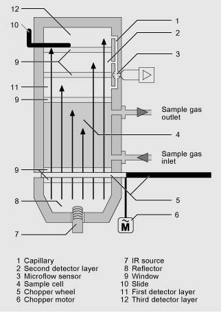
ULTRAMAT 23, principle of operation of the infrared channel (example with three-layer detector)
Automatic calibration with air
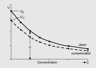
The ULTRAMAT 23 can be calibrated using, for example, ambient air. During this process (between 1 and 24 hours (adjustable), 0 = no AUTOCAL), the chamber is purged with air. The detector then generates the largest signal U0 (no pre-absorption in the sample chamber). This signal is used as the reference signal for zero point calibration, and also serves as the initial value for calculating the full-scale value in the manner shown below.
As the concentration of the measured component increases, so too does absorption in the sample chamber. As a result of this preabsorption, the detectable radiation energy in the detector decreases, and thus also the signal voltage. For the single-beam procedure of the ULTRAMAT 23, the mathematical relationship between the concentration of the measured component and the measured voltage can be approximately expressed as the following exponential function:
U = U0 · e-kc
c Concentration
k Device-specific constant
U0 Basic signal with zero gas (sample gas without measured component)
U Detector signal
Changes in the radiation power, contamination of the sample chamber, or ageing of the detector components have the same effect on both U0 and U, and result in the following:
U’ = U’0 · e-kc
Apart from being dependent on concentration c, the measured voltage thus changes continuously as the IR source ages, or with persistent contamination.
Each AUTOCAL tracks the total characteristic until the currently valid value, thereby compensating for temperature and pressure influences.
The influences of contamination and ageing, as mentioned above, will have a negligible influence on the measurement as long as U’ remains in a certain tolerance range monitored by the unit.
The tolerance "clamping width" between two or more AUTOCALs can be individually parameterized on the ULTRAMAT 23 and an alarm message output. A fault message is output when the value falls below the original factory setting of U0 < 50 % U. In most cases, this is due to the sample chamber being contaminated.
The units can be set to automatically calibrate the zero point every 1 to 24 hours, using ambient air or nitrogen. The calibration point for the IR-sensitive components is calculated mathematically from the newly determined U’o and the device-specific parameters stored as default values. It is recommendable to check the calibration point once a year using a calibration gas. (For details on TUV measurements, see Table "Calibration intervals (TUV versions)" under Selection and ordering data).
If an electrochemical sensor is installed, it is recommendable to use air for the AUTOCAL. In addition to calibration of the zero point of the IR-sensitive components, it is then also possible to simultaneously calibrate the calibration point of the electrochemical O2 sensor automatically. The characteristic of the O2 sensor is sufficiently stable following the single-point calibration such that the zero point of the electrochemical sensor needs only be checked once a year by connecting nitrogen.
Calibration
Oxygen measurement
The oxygen sensor operates according to the principle of a fuel cell. The oxygen is converted at the boundary layer between the cathode and electrolyte. An electron emission current flows between the lead anode and cathode and via a resistor, where a measured voltage is present. This measured voltage is proportional to the concentration of oxygen in the sample gas.
The oxygen electrolyte used is less influenced by interference influences (particularly CO2, CO, H2 and CH4) than other sensor types.
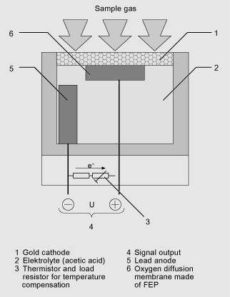
ULTRAMAT 23, principle of operation of the oxygen sensor
Electrochemical sensor for H2S determination
The hydrogen sulfide enters through the diffusion barrier (gas diaphragm) into the sensor and is oxidized at the working electrode. A reaction in the form of a reduction of atmospheric oxygen takes place on the counter electrode. The transfer of electrons can be tapped on the connector pins as a current which is directly proportional to the gas concentration.
Calibration
The zero point is automatically recalibrated by the AUTOCAL function when connecting e.g. nitrogen or air. It is recommendable to check the calibration point after 3 months using calibration gas (1 000 to 3 000 vpm).
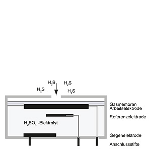
Operating principle of the H2S sensor
Paramagnetic oxygen cell
In contrast to other gases, oxygen is highly paramagnetic. This property is used as the basis for the method of measurement.
Two permanent magnets generate an inhomogeneous magnetic field in the measuring cell. If oxygen molecules flow into the measuring cell (1), they are drawn into the magnetic field. This results in the two diamagnetic hollow spheres (2) being displaced out of the magnetic field. This rotary motion is recorded optically, and serves as the input variable for control of a compensation flow. This generates a torque opposite to the rotary motion around the two hollow spheres by means of a wire loop (3). The compensation current is proportional to the concentration of oxygen.
The calibration point is calibrated using the AUTOCAL function by connecting oxygen (analogous to calibration of the electrochemical O2 sensor). In order to comply with the technical data, the zero point of the paramagnetic measuring cell must be calibrated with nitrogen weekly in the case of measuring ranges < 5% or every two months in the case of larger measuring ranges.
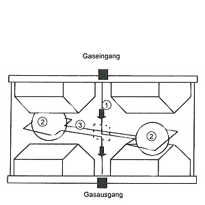
Operating principle of the paramagnetic oxygen cell
|
Accompanying gas |
Formula |
Deviation at 20 °C |
Deviation at 50 °C |
|---|---|---|---|
|
Acetaldehyde |
C2H4O |
-0.31 |
-0.34 |
|
Acetone |
C3H6O |
-0.63 |
-0.69 |
|
Acetylene, ethyne |
C2H2 |
-0.26 |
-0.28 |
|
Ammonia |
NH3 |
-0.17 |
-0.19 |
|
Argon |
Ar |
-0.23 |
-0.25 |
|
Benzene |
C6H6 |
-1.24 |
-1.34 |
|
Bromine |
Br2 |
-1.78 |
-1.97 |
|
Butadiene |
C4H6 |
-0.85 |
-0.93 |
|
n-butane |
C4H10 |
-1.1 |
-1.22 |
|
Iso-butylene |
C4H8 |
-0.94 |
-1.06 |
|
Chlorine |
Cl2 |
-0.83 |
-0.91 |
|
Diacetylene |
C4H2 |
-1.09 |
-1.2 |
|
Dinitrogen monoxide |
N2O |
-0.2 |
-0.22 |
|
Ethane |
C2H6 |
-0.43 |
-0.47 |
|
Ethyl benzene |
C8H10 |
-1.89 |
-2.08 |
|
Ethylene, ethene |
C2H4 |
-0.2 |
-0.22 |
|
Ethylene glycol |
C2H6O2 |
-0.78 |
-0.88 |
|
Ethylene oxide |
C2H4O |
-0.54 |
-0.6 |
|
Furan |
C4H4O |
-0.9 |
-0.99 |
|
Helium |
He |
0.29 |
0.32 |
|
n-hexane |
C6H14 |
-1.78 |
-1.97 |
|
Hydrogen chloride, hydrochloric acid |
HCl |
-0.31 |
-0.34 |
|
Hydrogen fluoride, hydrofluoric acid |
HF |
0.12 |
0.14 |
|
Carbon dioxide |
CO2 |
-0.27 |
-0.29 |
|
Carbon monoxide |
CO |
-0.06 |
-0.07 |
|
Krypton |
Kr |
-0.49 |
-0.54 |
|
Methane |
CH4 |
-0.16 |
-0.17 |
|
Methanol |
CH4O |
-0.27 |
-0.31 |
|
Methylene chloride |
CH2Cl2 |
-1 |
-1.1 |
|
Monosilane, silane |
SiH4 |
-0.24 |
-0.27 |
|
Neon |
Ne |
0.16 |
0.17 |
|
n-octane |
C8H18 |
-2.45 |
-2.7 |
|
Phenol |
C6H6O |
-1.4 |
-1.54 |
|
Propane |
C3H8 |
-0.77 |
-0.85 |
|
Propylene, propene |
C3H6 |
-0.57 |
-0.62 |
|
Propylene chloride |
C3H7Cl |
-1.42 |
-1.44 |
|
Propylene oxide |
C3H6O |
-0.9 |
-1 |
|
Oxygen |
O2 |
100 |
100 |
|
Sulfur dioxide |
SO2 |
-0.18 |
-0.2 |
|
Sulfur hexafluoride |
SF6 |
-0.98 |
-1.05 |
|
Hydrogen sulfide |
H2S |
-0.41 |
-0.43 |
|
Nitrogen |
N2 |
0 |
0 |
|
Nitrogen dioxide |
NO2 |
5 |
16 |
|
Nitrogen monoxide |
NO |
42.7 |
43 |
|
Styrene |
C8H8 |
-1.63 |
-1.8 |
|
Toluene |
C7H8 |
-1.57 |
-1.73 |
|
Vinyl chloride |
C2H3Cl |
-0.68 |
-0.74 |
|
Vinyl fluoride |
C2H3F |
-0.49 |
-0.54 |
|
Water (vapor) |
H2O |
-0.03 |
-0.03 |
|
Hydrogen |
H2 |
0.23 |
0.26 |
|
Xenon |
Xe |
-0.95 |
-1.02 |
Cross-sensitivities (with accompanying gas concentration 100%)
ULTRAMAT 23 essential characteristics
- Practically maintenance-free thanks to AUTOCAL with ambient air (or with N2, only for units without an oxygen sensor); both the zero point and the sensitivity are calibrated in the process
- Calibration with calibration gas only required every twelve months, depending on the application
- Two measuring ranges per component can be set within specified limits;
all measuring ranges linearized;
autoranging with measuring range identification - Automatic correction of variations in atmospheric pressure
- Sample gas flow monitoring;
error message output if flow < 1 l/min
(only with Viton sample gas path) - Maintenance request alert
- Two freely configurable undershooting or overshooting limit values per measured component