To complete the drive system, components such as motors and encoders must be connected to it via cables.
On motors with DRIVE?CLiQ interface, the 24 V DC power supply is provided via the DRIVE?CLiQ cables. On all other Sensor Modules, a separate 24 V DC power supply must be provided.
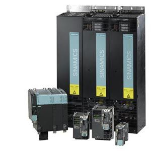
Drive connection system
Legend
Cable
Description
(1)
DRIVE?CLiQ cables
Standard cables for cabinet-internal configuration without 24 V cores
(2)
DRIVE?CLiQ MOTION?CONNECT 500/800 cables
MOTION?CONNECT 500 shielded cables with 24 V cores for fixed installation (e.g. in the cable duct), and MOTION?CONNECT 800 for flexible installation (e.g. in cable carriers)
(3)
MOTION?CONNECT 500/800 signal cables
Suitable for the measuring system in question; in versions MOTION?CONNECT 500 for fixed installation (e.g. in the cable duct), and MOTION?CONNECT 800 for flexible installation (e.g. in cable carriers)
(4)
MOTION?CONNECT 500/800 power cables
MOTION?CONNECT 500 shielded motor cables for fixed installation (e.g. in the cable duct), and MOTION?CONNECT 800 for flexible installation (e.g. in cable carriers)
DRIVE?CLiQ cables are available in various designs and lengths (see MOTION?CONNECT connection system).
The required bending radii apply particularly to short cables. In addition to the distance between the two DRIVE?CLiQ sockets to be connected by the cable, a cable length of at least 60 mm (2.36 in) must be allowed for the bending radii. For definition of lengths of pre-assembled cables, refer to chapter MOTION?CONNECT connection systems.
Unused DRIVE?CLiQ sockets can be protected with a blanking plug. Suitable blanking plugs are supplied in the accessories pack for the units.
Mechanical configuration of the drive
A SINAMICS S drive line-up comprises a Line Module, Motor Modules, DC link components, a Control Unit, and the optional expansion modules.
Configuration of a drive line-up in booksize format
The following criteria must be taken into account when a drive line-up of booksize format units is configured:
The Smart Line Modules 5 kW and 10 kW must always be arranged on the left as the first module, and all other Line Modules should be arranged on the left as the first module. The CU320?2 Control Unit in this case can be "snapped onto" the left-hand side of the Line Module.
The DC link busbars can be connected on the right and left with Basic Line Modules, Active Line Modules and Smart Line Modules rated from 16 kW. In this case, the drive can be configured in the reverse order (from right to left) or on both sides (see arrangement for chassis format units).
Only one Line Module is permitted in each drive line-up.
A number of drive line-ups must be configured for power supplies which cannot be provided by the highest rating.
The Motor Modules must be arranged beside the Line Module in descending order of the rated currents, that is, the Motor Module with the highest rated current is to be mounted immediately adjacent to the Line Module, and the Motor Module with the lowest rated current is positioned furthest away from the Line Module.
DC link busbars are integrated into the Line Modules, Motor Modules, Braking Modules, Capacitor Modules, Control Supply Modules and Voltage Clamping Modules for connecting the drive line-up. The current carrying capacity of the integral DC link busbars depends on the power rating of the module and is 100 A or 200 A (see technical specifications). Within the drive line-up, it must be ensured that the DC link busbars meet the current-carrying capacity requirements at every point in the drive line-up. When high-power Motor Modules (200 A DC link busbars) and low-power Motor Modules (100 A DC link busbars) are used together, the Braking Module for example (100 A DC link busbars) must be installed after the high-power Motor Modules.
DC link adapters can be used to implement multi-tier configurations.
The drive line-ups should be configured such that the total length of all power cables for the motor cables and the line cable, which should preferably be shielded, in each individual line-up does not exceed the permissible total cable length.
Power-oriented arrangement of booksize format Motor Modules
The Control Unit configuration is flexible. The following configuration options are possible:
"Docking" on the left-hand side of the Line Module
Direct mounting next to the drive line-up on a mounting plate
Mounting in other cabinet areas, taking the permissible DRIVE?CLiQ cable lengths into account
Configuration of a drive line-up in chassis format
The Motor Modules must be positioned to the left or right of the Line Module with decreasing rated currents (i.e. the Motor Module with the highest rated current is positioned next to the Line Module on the left or right, while the Motor Module with the lowest rated current is at the end). You must ensure that the cables/busbars for the DC link meet the current-carrying capacity requirements for all connected Motor Modules.
The inductance of the DC link busbars must be low, achieved, for example, by arranging the bars as close as possible in parallel, but observing the required creepage distances and air gaps.
The Control Unit configuration is flexible. The following configuration options are possible:
"Docking" on the left-hand side of the Line Module
Direct mounting next to the drive line-up on a mounting plate
Mounting in other cabinet areas, taking the permissible DRIVE?CLiQ cable lengths into account
Configuration of a mixed drive line-up in chassis and booksize formats
A mixed drive line-up must be configured according to the rules for chassis format units. The Motor Modules in booksize format can be connected to the higher-level DC link busbars by means of DC link rectifier adapters. With (A), each Motor Module in booksize format is connected using the appropriate DC link rectifier adapter. With (B), Motor Modules in booksize format are connected to one another with the internal DC link busbars and a DC link rectifier adapter is used on the last Motor Module to make the connection to the higher-level DC link busbars. In the latter case, the DC link rectifier adapter must be attached to the last Motor Module on the right-hand side of the line. As regards the arrangement of modules with different current ratings, the guidelines specified under "Configuration of a drive line-up in booksize format" also apply to mixed drive line-ups.
Ideally, the entire length of the higher-level DC link busbars can be dimensioned for the rated DC link current of the Line Module. The busbars are then protected by the line fuses at the infeed end.
If the cross section of the DC link busbars or cabling is reduced, this branch must be designed to be short-circuit-proof. The current limiting mechanism of the Motor Modules connected to the branch with reduced cross section then protects it against overloading. It is not advisable to reduce busbars or cables down to the mandatory minimum cross section. No additional overload protection (fuse) is required on the assumption that overloading cannot occur as a result of cable damage on the cable route to the Motor Module and that the circuit branch is protected against overloading by the Motor Module.
Where the cross section has been significantly reduced, or the circuit design is not inherently short-circuit-proof, a branch fuse must be installed at the beginning of the section with reduced cross section in order to protect the DC link connections involved. In the event of a fault, the fuse must be capable of interrupting DC fault currents; other types of miniature circuit breaker are not suitable.
Allocation of branch fuses for option (A) in a supply system with grounded neutral (TN system). The calculations are based on the assumption that ? = L/R < 10 ms applies to the time constant ? in the DC fault circuit and that the fault current is interrupted by the fuse after maximum 1 s.
Motor Module booksize format Irated
Recommended cable cross section for Cu conductors and PVC insulation with a permissible operating temperature of 70 °C (158 °F) on the conductor