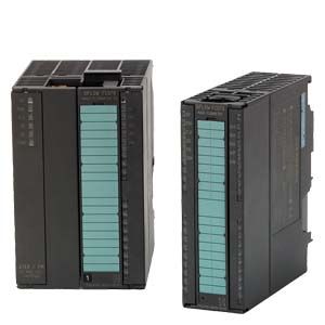
Measurement of | Mass flow, volume flow, density, sensor temperature, fraction A flow, fraction B flow, fraction A in % |
Measurement functions | |
| Totalization of mass flow, volume flow, fraction A, fraction B |
| Totalization of mass flow, volume flow, fraction A, fraction B |
- Single and 2-stage batch function
| Batching function with the use of one or two outputs for dosing in high and low speed |
| 4 programmable high/low limits for mass flow, volume flow, density, sensor temperature, fraction A flow, fraction B flow, fraction A in %. Limits will generate an alarm if reached. |
Digital input | |
Functions | Start batch, stop batch, start/stop batch, hold/continue batch, reset totalizer 1, reset totalizer 2, reset totalizer 1 and 2, zero adjust, force frequency output, freeze frequency output |
High signal | - Nominal voltage: 24 V DC
- Lower limit: 15 V DC
- Upper limit: 30 V DC
- Current: 2 … 15 mA
|
Low signal | - Nominal voltage: 0 V DC
- Lower limit: -3 V DC
- Upper limit: 5 V DC
- Current: -15 … +15 mA
|
Input | Approx. 10 k? |
Switching | Max. 100 Hz |
Digital output 1 and 2 | |
Functions | - Output 1:
Pulse, frequency, redundancy pulse, redundancy frequency 2-stage batch, batch - Output 2:
Redundancy pulse, redundancy frequency, 2-stage batch
|
Voltage supply | 3 … 30 V DC (passive output) |
Switching current | Max. 30 mA at 30 V DC |
Voltage drop | ? 3 V DC at max. current |
Leakage current | ? 0.4 mA at max. voltage 30 V DC |
Load resistance | 1 … 10 k? |
Switching frequency | 0 … 12 kHz 50 % duty cycle |
Functions | Pulse, frequency, redundancy pulse, redundancy frequency 2-stage batch, batch |
Communication | |
Modbus RS 232C | - Max. baud rate: 115 200 baud
- Max. line length: 15 m at 115 200 baud
- Signal level: according to EIA-RS 232C
|
Modbus RS 485 | - Max. baud rate: 115 200 baud
- Max. line length: 1200 m at 115 200 baud
- Signal level: according to EIA-RS 485
- Bus termination: Integrated. Can be enabled by inserting wire jumpers.
|
Galvanic isolation | All inputs, outputs and communication interfaces are galvanically isolated. Isolation voltage: 500 V. |
Power | |
Supply | 24 V DC nominal |
Tolerance | 20.4 V DC … 28.8 V DC |
Consumption | Max. 7.2 W |
Fuse | T1 A/125 V, not replaceable by operator |
Environment | |
Ambient temperature | - Storage -40 °C … +70 °C (-40 °F … +158 °F)
|
Operation conditions | Horizontally mounted rail.
For SIFLOW FC070 Std.: 0 … 60 °C (32 … 140 °F)
For SIFLOW FC070 Ex CT:
-40 … +60 °C (-40 … +140 °F) Vertically mounted rail
For SIFLOW FC070 Std.:
0 … 45 °C (32 … 113 °F)
For SIFLOW FC070 Ex CT:
-40 … +45 °C (-40 … +113 °F) |
Altitude | - Operation: -1000 … 2000 m
(pressure 795 … 1080 hPa)
|
Enclosure | |
Material | Noryl, color: anthracite |
Rating | IP20/NEMA 2 according to IEC 60529 |
Mechanical load | According to SIMATIC standards (S7-300 devices) |
Ex approvals | |
SIFLOW FC070 Standard | ATEX: II 3G Ex nA II T4 |
SIFLOW FC070 Ex CT | ATEX, IECEx, EAC Ex, FM, CSA, NEPSI, INMETRO: |
- Zone 2: Ex nA [ia] IIC T4
|
FM: |
- Class I, Div. 2:
Grp. A, B, C, D (interface to Class I+II+III, Div. 1)
|
Custody transfer approvals | |
SIFLOW FC070 Ex CT | PTB Germany approval no.: 5.4.11/11.22
OIML R 139 - Compressed gaseous fuel measuring systems for vehicles
NTEP for USA and Canada, approval no: 97-111A3 |
EMC performance | |
Emission | EN 55011/CISPR-11 |
Immunity | EN/IEC 61326-1 |
NAMUR | Within the limits according to “General recommendations” with error criteria A in accordance with NE 21 |
Programming tools | |
SIMATIC S7 | Configuration through backplane P-BUS, PLC program and WinCC flexible |
SIMATIC PCS7 | Configuration trough backplane P-BUS and PLC/WinCC faceplates, certified driver |
SIMATIC PDM | Through Modbus port RS 232C and RS 485, certified driver |


