
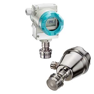
SITRANS P, DS III seriesxxx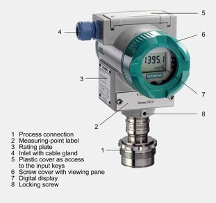
Device front view, SITRANS P DS III The transmitter comprises a range of different components, depending on the order specifications. The various options are listed in the ordering information. The components described below are the same for all transmitters. The rating plate (3, Figure "Front view") with the Order No. is located on the side of the housing. The specified number together with the ordering information provide details on the optional design details and on the possible measuring range (physical properties of built-in sensor element). The approval label is located on the opposite side. The housing is made of die-cast aluminium or stainless steel precision casting. A round cover is screwed on at the front and rear of the housing. The front cover (6) can be fitted with a viewing pane so that the measured values can be read directly on the digital display. The inlet (4) for the electrical connection is located either on the left or right side. The unused opening on the opposite side is sealed by a blanking plug. The protective earth connection is located on the rear of the housing. The electrical connections for the power supply and screen are accessible by unscrewing the rear cover. The bottom part of the housing contains the measuring cell with process connection (1). The measuring cell is prevented from rotating by a locking screw (8). As the result of this modular design, the measuring cell and the electronics can be replaced separately from each other. The set parameter data are retained. At the top of the housing is a plastic cover (5), which hides the input keys. SITRANS P300The device comprises:
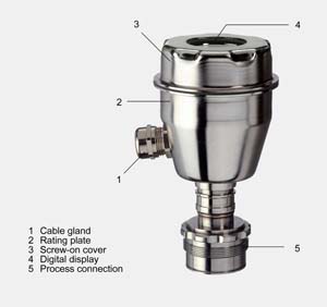
Perspective view of the SITRANS P300 The housing has a screwable cover (3), with or without an inspection window depending on the version. The electrical terminal housing, the buttons for operation of the device and, depending on the version, the digital display are located under this cover. The connections for the auxiliary power UH and the shield are in the terminal housing. The cable gland is on the side of the housing. The measuring cell with the process connection (5) is located on the underside of the housing. Depending on the version of the device, the measuring cell with the process connection may differ from the one shown in the diagram. Example for an attached measuring point label
|
| Каталог 2018 | Каталог 2017 | Каталог 2016 | Каталог 2015 | Каталог 2014 | Каталог 2013 | Каталог 2012 | Сертификат | Контакты | Карта сайта | Поиск |